Four-stroke four-cylinder opposed one-way rotary engine and control method thereof

A one-way rotation, four-stroke technology, applied in the direction of machines/engines, mechanical equipment, etc., can solve the problems of insufficient combustion of oil cylinders, large exhaust gas emissions, and low heat engine efficiency of internal combustion engines, and achieve full combustion, low exhaust gas emissions, and structural simple effect

Pending Publication Date: 2019-01-11
苏州智一新能源动力系统有限公司
View PDF1 Cites 11 Cited by
  • Summary
  • Abstract
  • Description
  • Claims
  • Application Information

AI Technical Summary

Problems solved by technology

[0003] The purpose of the present invention is to provide a four-stroke four-cylinder opposed one-way rotary engine and its control method to solve the problems of low thermal efficiency of existing internal combustion engines, insufficient combustion of oil cylinders, and large exhaust emissions

Method used


Image

  • Four-stroke four-cylinder opposed one-way rotary engine and control method thereof
  • Four-stroke four-cylinder opposed one-way rotary engine and control method thereof
  • Four-stroke four-cylinder opposed one-way rotary engine and control method thereof

Examples


Embodiment 1

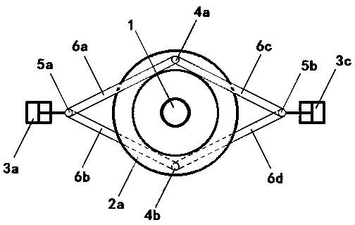
[0035] see figure 1 and figure 2 As shown, a four-stroke four-cylinder opposed one-way rotary engine includes an output shaft 1, a first one-way wheel 2a, a second one-way wheel 2b, a first oil cylinder 3a, a second oil cylinder 3b, a third oil cylinder 3c, The fourth oil cylinder 3d, the first connecting rod 5a, the second connecting rod 5b, the first push-pull rod 6a, the second push-pull rod 6b, the third push-pull rod 6c and the fourth push-pull rod 6d.

[0036] Both the first one-way wheel 2a and the second one-way wheel 2b adopt the applicant’s previous application number 201821139491.8 "a kind of one-way impact wheel" patent; the first one-way wheel 2a and The second one-way wheels 2b are both sleeved on the output shaft 1, and the effective rotation directions of the first one-way wheels 2a and the second one-way wheels 2b are the same; the first one-way wheels The upper or lower end of the outer surface of 2a is provided with a first hinge point 4a, and the lower o...

Embodiment 2

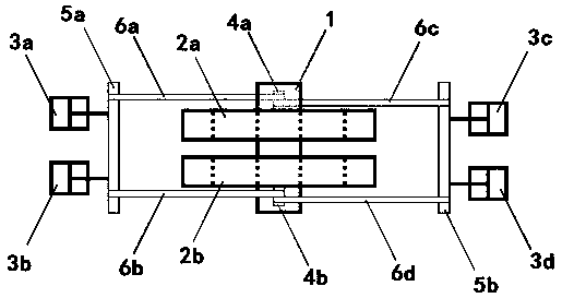
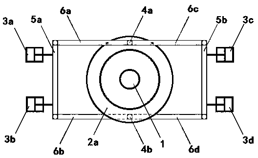
[0045] see image 3 and Figure 4 As shown, a four-stroke four-cylinder opposed one-way rotary engine includes an output shaft 1, a first one-way wheel 2a, a second one-way wheel 2b, a first oil cylinder 3a, a second oil cylinder 3b, a third oil cylinder 3c, The fourth oil cylinder 3d, the first connecting rod 5a, the second connecting rod 5b, the first push-pull rod 6a, the second push-pull rod 6b, the third push-pull rod 6c and the fourth push-pull rod 6d.

[0046] Both the first one-way wheel 2a and the second one-way wheel 2b adopt the applicant’s previous application number 201821139491.8 "a kind of one-way impact wheel" patent; the first one-way wheel 2a and The second one-way wheels 2b are both sleeved on the output shaft 1, and the effective rotation directions of the first one-way wheels 2a and the second one-way wheels 2b are the same; the first one-way wheels The upper or lower end of the outer surface of 2a is provided with a first hinge point 4a, and the lower o...


PUM


Abstract

The invention discloses a four-stroke four-cylinder opposed one-way rotary engine and a control method thereof. The engine consists of an output shaft, two one-way wheels, four oil cylinders, two connecting rods and four push-pull rods. The control method for the engine comprises the following steps of: enabling the four oil cylinders to ignite in turns; enabling the two one-way wheels to performcirculating motion between positive rotation and negative rotation by utilizing the push-pull rods connected between the oil cylinders and the one-way wheels, enabling other three oil cylinders to separately complete action of gas exhaust, gas inlet and compression while the output shaft is driven to perform power output. The four-stroke four-cylinder opposed one-way rotary engine adopts the connecting rods and the push-pull rods as transmission mechanisms, the four oil cylinders are oppositely arranged in pairs, and twisting force output of the output shaft and return for the push-pull rods are simultaneously realized by utilizing in-turn ignition power of the four oil cylinders and one-way locking property of the two one-way wheels. The four-stroke four-cylinder opposed one-way rotary engine has the advantages of being simple in structure, small in size, low in cost, reliable in work, high in efficiency of the heat engine, flexible in application, strong in universality and the like.

Description

technical field [0001] The invention belongs to the technical field of automobile engines, and relates to a fuel engine, in particular to a four-stroke four-cylinder opposed one-way rotary engine and a control method thereof. Background technique [0002] At present, fuel engines all over the world are reciprocating engines using a crankshaft as a transmission mechanism. Among the many reciprocating engines, the four-stroke engine is the most classic. The four actions of the cylinder are air intake, compression, ignition and exhaust, and the piston in the cylinder can reciprocate through the linkage of the crankshaft. Form a steady stream of motivation. Most of the existing four-stroke engines are arranged in-line, V-type or W-type. This type of reciprocating engine often has a complex design structure, and the noise is large when accelerating, especially in the dead zone of the oil cylinder and the crankshaft. The 180 degree and 180 degree zones lose power, not only is it...

Claims


Application Information

Patent Timeline
Patent Type & Authority Applications(China)
IPC IPC(8): F02B75/02F02B75/24F02B75/32
CPCF02B75/02F02B75/24F02B75/32F02B2075/027F02B2075/1816
Inventor 樊朝晖
Owner 苏州智一新能源动力系统有限公司
Why Eureka
Try Eureka