Gravity energy storage system

An energy storage system and gravity technology, applied in the direction of machines/engines, mechanical equipment, engines, etc., can solve the problems of being unable to bear tens of thousands or even hundreds of thousands of tons of pressure, high investment ratio, low utilization rate of lifting equipment, etc.

Inactive Publication Date: 2019-01-11
张智蓬
View PDF0 Cites 2 Cited by
  • Summary
  • Abstract
  • Description
  • Claims
  • Application Information

AI Technical Summary

Problems solved by technology

And an energy storage solution that uses lifting heavy objects to store energy. This solution needs to build a lifting system with a height of 100 to 200 meters and a lifting weight of tens of thousands of tons. There is no problem with the realization and construction of the technology. The problem is the lifting equipment The utilization rate of the battery is low because it can only be charged and discharged once a day. If you want to improve the utilization rate of the equipment, you must set up places for placing counterweights for energy storage at the upper and lower ends, so that you can charge or discharge several times. Improve the utilization rate of lifting equipment, so that the investment ratio of hundreds of meters high man-made structures with tens of thousands of tons of energy storage blocks will be very high, unless the cli...

Method used


Image

  • Gravity energy storage system
  • Gravity energy storage system
  • Gravity energy storage system

Examples


Embodiment 1

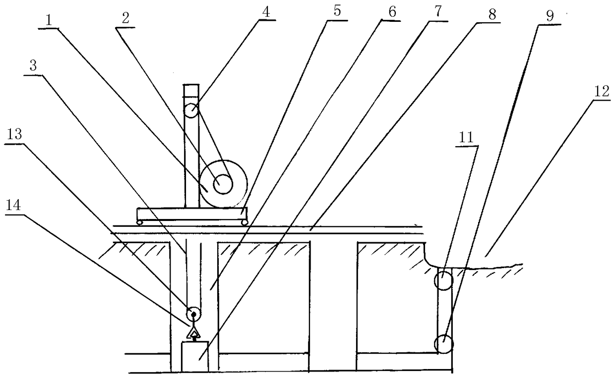
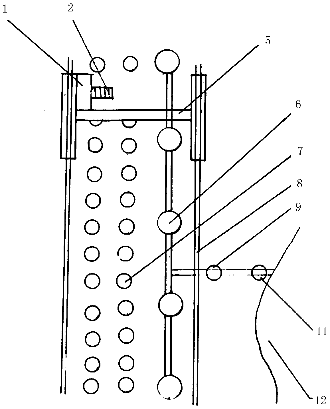
[0024] Such as figure 1 , 2 As shown, there are at least two vertical shafts 6 underground. The vertical shafts are arranged in a straight line, and the bottoms of the multiple vertical shafts are connected. The structural environment and design capacity are for reference, about 200 meters to 600 meters; the passage at the bottom of the shaft is equipped with a two-way water pump 9, and the two-way water pump 9 is connected to the upper pool 12 on the ground through a water pipe 10 and a water valve 11; there is a track above the shaft 8. There is a gantry crane 5 running on the track, and the hoisting motor 1 is installed on the base of the lower part of the gantry crane, and the hoisting motor 1 can be switched between a generator and a motor. The hoisting motor is connected with a winding drum, and the hoisting motor drives the winding drum 2 to rotate, and the winding drum 2 is wound with a steel wire rope 3, and the rear end of the steel wire rope 3 is fixed on the main ...


PUM


Abstract

The invention relates to a gravity energy storage system. According to the structure of the gravity energy storage system, at least two vertical shafts are built underground, and the bottoms of the vertical shafts mutually communicate; a bidirectional water pump is arranged on a channel at the bottom of each vertical shaft, and each bidirectional water pump is connected with an upper water tank onthe ground through a water pipe and a water valve; rails are arranged above each vertical shaft, a gantry crane is arranged on the rails, and a lifting motor is installed on a base at the lower partof the gantry crane; the lifting motor is connected with a winding drum and drives the winding drum to rotate, and a steel wire rope is wound on the winding drum; and the steel wire rope penetrates through a fixed pulley set on the gantry crane and the rear tail end of a movable pulley set to be fixed on a gantry crane main beam on the upper portion of the gantry crane, a lifting appliance is arranged below the movable pulley set, and an energy storage block is hooked through the lifting appliance. According to the gravity energy storage system, electric power can be smoothly output, the occupied area is small, site selection is easy to achieve, no emission exists, pollution is avoided, the storage power is high, the efficiency is high, the service life is long, the problem of new energy grid connection can be effectively solved, and power fluctuation reduction can be effectively reduced.

Description

technical field [0001] The invention relates to the field of electric energy storage, in particular to a gravity energy storage system. Background technique [0002] The bottleneck restricting new energy grid integration is the lack of energy storage, the lack of energy storage technology, and the lack of energy storage electricity price mechanism. In the final analysis, there is still a lack of energy storage. No matter what kind of energy is developed, if we want to achieve energy conservation, environmental protection, and maintenance of the grid Safety and the development of energy storage are essential. The country's energy storage development direction is to develop electric new energy vehicles. Using the huge automobile market as a storage pool for the power grid can achieve multiple carvings with one sword. The bottleneck is the research and development of cheap Low temperature resistance, long battery life, and fast charging battery technology, as well as the develo...

Claims


Application Information

Patent Timeline
IPC IPC(8): F03G3/00
CPCF03G3/00
Inventor 张智蓬张成革
Owner 张智蓬
Why Eureka
Try Eureka