Data center cold and heat combined supply large temperature difference heat supply system combined with boiler

A data center and heating system technology, applied in heating systems, household heating, heating fuel, etc., can solve the problem of high investment and operating costs of the pipeline network, the inability of direct heat exchange of the return water of the heating network, and the high cost of waste heat recovery and other issues, to achieve high energy utilization efficiency, reduce transformation workload, and low operating costs

Pending Publication Date: 2019-01-11
CHINA INST OF BUILDING STANDARD DESIGN & RES
View PDF0 Cites 3 Cited by
  • Summary
  • Abstract
  • Description
  • Claims
  • Application Information

AI Technical Summary

Problems solved by technology

At the same time, due to environmental protection requirements, the newly built data center is far away from the city. If you want to use the waste heat of the data center, you need to build a long-distance hot water pipe network to realize heat transmission, and the return water temperature of the conventional heating network is relatively high, usually 40 ℃ ~ 50 ℃ , resulting in two problems: (1) Due to the small temperature difference between the heating network supply and return water and the large flow rate, the pipe network investment and operating costs of the waste heat heating project in the data center are high; (2) The return water of the heating network cannot be compared with the The waste heat of the cooling water in the data center is directly exchanged, and the cost of waste heat recovery is high

Method used


Image

  • Data center cold and heat combined supply large temperature difference heat supply system combined with boiler
  • Data center cold and heat combined supply large temperature difference heat supply system combined with boiler

Examples


Embodiment Construction

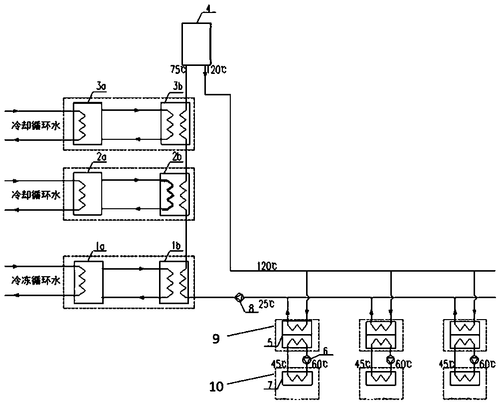
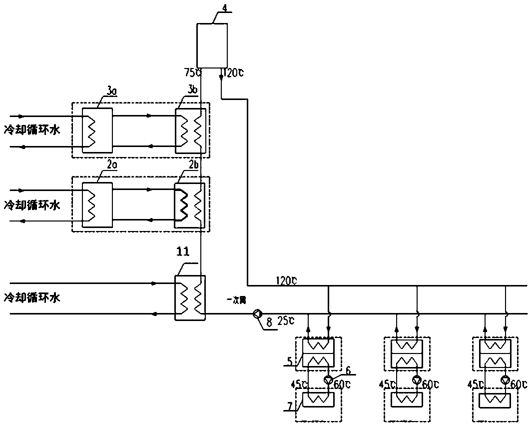
[0021] Hereinafter, embodiments of the combined cooling and heating waste heat central heating system with large temperature difference utilizing data center waste heat according to the present invention will be described with reference to the accompanying drawings.

[0022] The examples described here are specific specific implementations of the present invention, and are used to illustrate the concept of the present invention. They are all explanatory and exemplary, and should not be construed as limiting the implementation of the present invention and the scope of the present invention. In addition to the embodiments described here, those skilled in the art can also adopt other obvious technical solutions based on the claims of the application and the contents disclosed in the description, and these technical solutions include adopting any obvious changes made to the embodiments described here. Replacement and modified technical solutions.

[0023] The accompanying drawings...


PUM


Abstract

The invention discloses a data center cold and heat combined large temperature difference heat supply system combined with a boiler, comprising a conventional water chilling unit, a compression type heat pump, the boiler, a water heating type absorbing heat exchange unit and related pipelines and accessories, wherein the conventional water chilling unit is used for extracting afterheat of a data center by refrigerating circulating water on evaporator side and dissipating heat in two paths on the condenser side, wherein one path is used for heating return water of a primary heat supply network,and the other path is connected to a compression heat pump evaporator to be used as a low-position heat source of the heat pump; the return water is heated stage by stage by a condenser, the evaporator absorbs the afterheat of cooling circulating water which returns to the conventional water chilling unit after heat exchange in the compression heat pump evaporator; the boiler heats the return water of the heat supply network to the heat supply temperature and then sending the water out of the data center through a heat supply and water supply pipeline; and supplied water of the heat supply network passes through the heat exchange unit and dissipates heat to a terminal user. The data center cold and heat combined large temperature difference heat supply system adopts the cold and heat combined supply, which creates conditions for utilizing low-grade heat energy or even waste heat and afterheat and the like, thereby greatly reducing the heating cost.

Description

technical field [0001] The invention belongs to the technical field of low-grade industrial waste heat utilization, and relates to a data center combined cold and heat supply and large temperature difference heating system combined with a boiler. Background technique [0002] In recent years, due to the pressure of environmental protection, the demand for clean heating has exploded, resulting in a shortage of clean heating sources in many areas in northern my country. At the national level, the important decisions of "promoting clean heating in winter in northern regions" and "resolutely fighting the battle to defend the blue sky" have also been put forward, requiring the use of clean energy as much as possible, accelerating the increase in the proportion of clean heating, and accelerating the resolution of coal-burning pollution. [0003] In recent years, due to the vigorous development of the Internet of Things, artificial intelligence, and big data industries, the scale o...

Claims


Application Information

Patent Timeline
Patent Type & Authority Applications(China)
IPC IPC(8): F24D12/02
CPCF24D12/02F24D2200/32Y02B30/00
Inventor 麦东道贾会超李本强王明明
Owner CHINA INST OF BUILDING STANDARD DESIGN & RES
Why Eureka
Try Eureka