
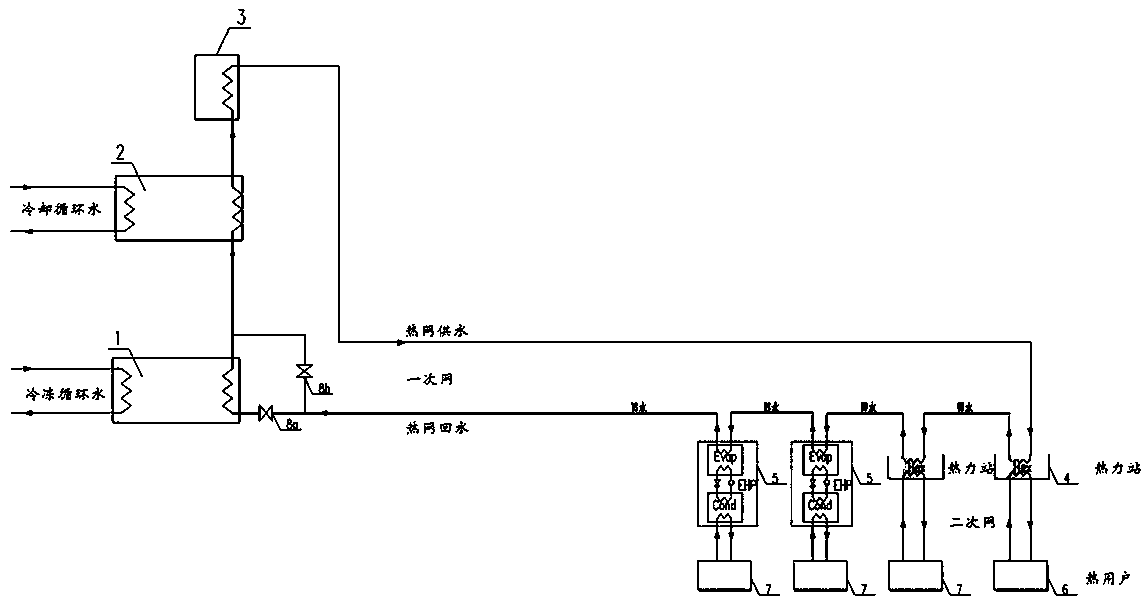
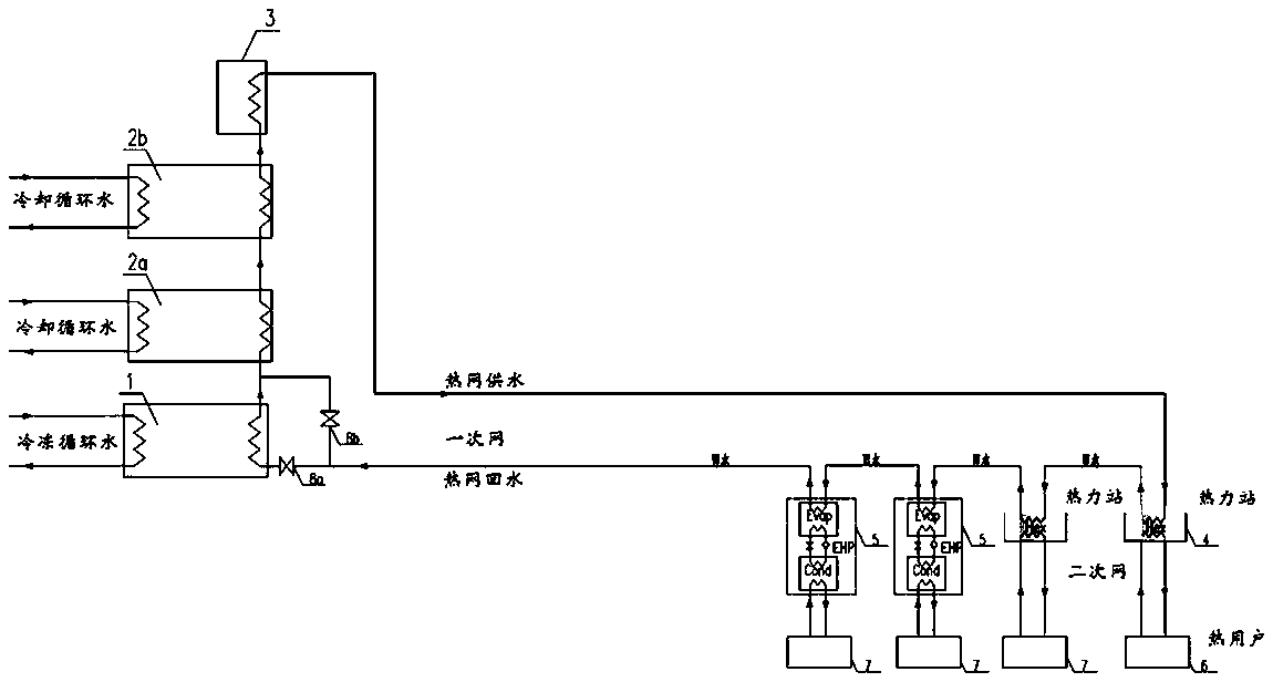
Data center cold and heat combined supply waste heat large-temperature-difference central heating system

A data center, combined cooling and heating technology, applied in the field of industrial waste heat utilization, can solve the problems of insufficient central heating network transmission capacity, limited waste heat recovery, and high heating costs, achieving high energy utilization efficiency, reducing evaporation loss, and running low cost effect

Pending Publication Date: 2018-07-24
CHINA INST OF BUILDING STANDARD DESIGN & RES
View PDF3 Cites 13 Cited by
  • Summary
  • Abstract
  • Description
  • Claims
  • Application Information

AI Technical Summary

Problems solved by technology

[0016] 3) The bottleneck problem of insufficient transmission capacity of the centralized heating network, the flow rate of circulating cooling water or the flow rate of the transmission and distribution pipe network and the matching of the operating flow rate of the heat pump;
[0018] 5) The high heating cost affects the popularization of clean heat source heating
However, the system is relatively complex, the heat transfer temperature difference between the cooling liquid and the circulating liquid is small, the waste heat recovery will be limited, and the transmission and distribution energy consumption of the heating pipe network is high, so it is difficult to popularize and apply it on a large scale

Method used


Image

  • Data center cold and heat combined supply waste heat large-temperature-difference central heating system
  • Data center cold and heat combined supply waste heat large-temperature-difference central heating system

Examples


Embodiment Construction

[0043] Hereinafter, embodiments of the combined cooling and heating waste heat central heating system with large temperature difference utilizing data center waste heat according to the present invention will be described with reference to the accompanying drawings.

[0044] The examples described here are specific specific implementations of the present invention, and are used to illustrate the concept of the present invention. They are all explanatory and exemplary, and should not be construed as limiting the implementation of the present invention and the scope of the present invention. In addition to the embodiments described here, those skilled in the art can also adopt other obvious technical solutions based on the claims of the application and the contents disclosed in the description, and these technical solutions include adopting any obvious changes made to the embodiments described here. Replacement and modified technical solutions.

[0045] The accompanying drawings...


PUM


Abstract

The invention provides a data center cold and heat combined supply waste heat large-temperature-difference central heating system which comprises a conventional water cooling unit, compression heat pumps, a peak adjusting heat source, a water-water heat exchanger, electricity-driven compression heat pumps, a connecting pipeline and an accessory. Data center waste heat is extracted through frozen circulating water on the evaporator side, heat release is conducted in two ways on the evaporator side, heat of one of the two ways heats a primary heating network return water, heat of the other way is connected into all stages of compression heat pump evaporators to serve as low-level heat sources of the heat pumps, and surplus heat is discharged into the environment through a cooling tower. Thecompression heat pumps conduct heat release in a condenser to heat the primary heating network return water stage by stage. The peak adjusting heat source heats the heating network return water to theheating temperature finally, and then the heating network return water is sent out of the data center through a heating pipeline. The heating network supplied water passes through the water-water heat exchanger to heat a terminal radiator user firstly and then flows into the electricity-driven compression heat pumps in series to heat the tail end of a radiation floor. According to the central heating system, cold and heat combined supply and cascaded heating are adopted, the primary heating network temperature difference is large, and only electricity is needed to serve as driving energy of the heat pumps.

Description

technical field [0001] The invention relates to the technical field of industrial waste heat utilization, in particular to a centralized heating system with large temperature difference of waste heat combined cold and heat supply in a data center. Background technique [0002] In 2014, the urban heating area in northern my country reached 12 billion square meters, of which the urban centralized heating area was 7.1 billion square meters. Heating energy consumption exceeds 180 million tons of standard coal (coal accounts for about 90%), which not only consumes a lot of energy, but also brings serious environmental problems. It is one of the main causes of winter smog in northern my country. In the heating season of 2017-2018, due to the rapid progress of the "coal-to-gas" clean heating renovation project in the northern region, the gas source could not keep up, resulting in a nationwide gas shortage. At the same time, there are still about 300 million tons of standard coal l...

Claims


Application Information

Patent Timeline
Patent Type & Authority Applications(China)
IPC IPC(8): F24D3/18
CPCF24D3/18
Inventor 麦东道
Owner CHINA INST OF BUILDING STANDARD DESIGN & RES
Learn More