
Sintering cooling device

A technology of cooling device and cooling pipe, which is applied in the field of sintering furnace, can solve problems such as leakage of welding joints of cooling coil pipes, influence of maintenance on production efficiency, and rise of cooling water temperature, so as to achieve metal fatigue resistance, small thermal stress, The effect of quality assurance

Pending Publication Date: 2019-01-11
SUZHOU HUIKE EQUIP CO LTD
View PDF7 Cites 1 Cited by
  • Summary
  • Abstract
  • Description
  • Claims
  • Application Information

AI Technical Summary

Problems solved by technology

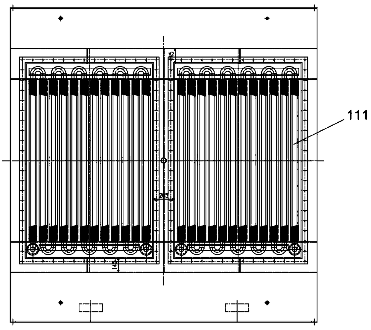
[0004] Among them, the rapid cooling device can quickly cool the sintered parts to the temperature of the furnace without oxidation. Since the sintered parts have components or powder materials, they cannot directly contact the cooling liquid. Generally, cooling coils 11 are used, such as figure 1 As shown, there is circulating cooling water inside, and the heat exchange between the outside and the cooling section achieves the purpose of cooling. The temperature of the sintered parts is extremely high, so the temperature of the cooling water will also rise sharply during heat exchange. In the continuous heat exchange, the heat The stress is also extremely high, which often leads to leakage problems at the joints or welds of the internal cooling coil. The general service life is about half a year, and there are problems. Half a year of maintenance greatly affects production efficiency. There is no solution in the industry

Method used


Image

  • Sintering cooling device
  • Sintering cooling device
  • Sintering cooling device

Examples


Embodiment Construction

[0023] The present invention will be further described below in conjunction with the accompanying drawings and specific embodiments, so that those skilled in the art can better understand the present invention and implement it, but the examples given are not intended to limit the present invention.

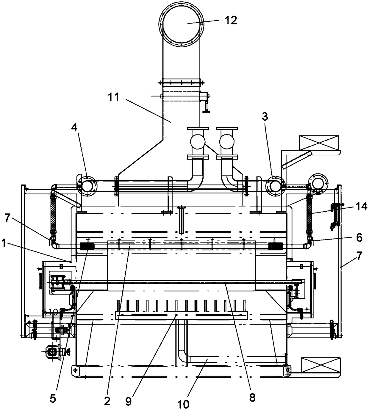
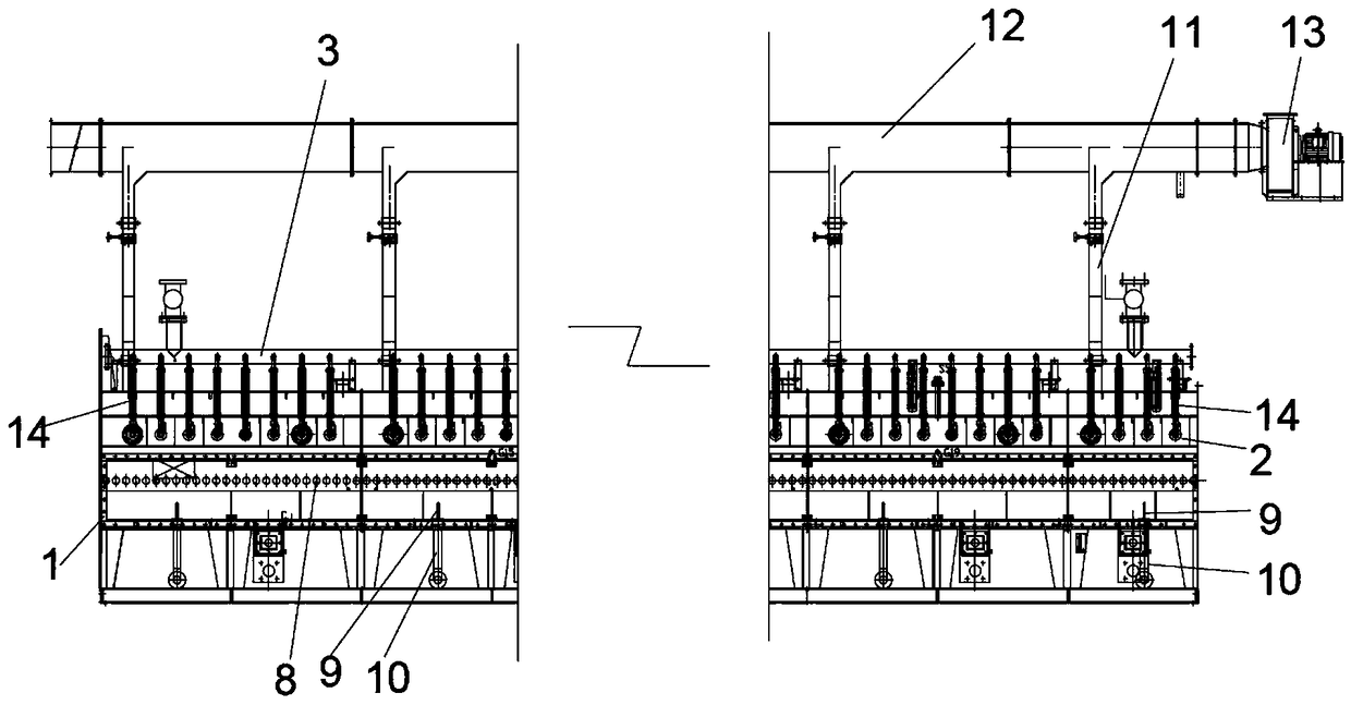
[0024] refer to Figure 2 to Figure 4 As shown, an embodiment of the sintering cooling device of the present invention includes a cooling furnace body 1, a plurality of cooling pipes 2 are arranged in the cooling furnace body 1, the cooling pipes 2 are seamless pipes, and the two ends of the cooling pipes 2 respectively pass through corresponding The inner wall of the cooling furnace body 1 is arranged to the outside, and one end of the seamless pipe is connected with the water inlet main pipe 3, and the other end is connected with the water outlet main pipe 4. Cooling pipes 2 are provided with cooling fins 5 on the surface inside the cooling furnace body 1 to accelerate heat exch...


PUM


Abstract

The invention discloses a sintering cooling device. The sintering cooling device comprises a cooling furnace body, multiple cooling pipes are arranged in the cooling furnace body, and are seamless pipes, two ends of the cooling pipes penetrate through the corresponding inner wall of the cooling furnace body to the outer portion, one ends of the cooling pipes are connected with a water inlet main pipe, and the other ends of the cooling pipes are connected with a water outlet main pipe. The sintering cooling device has the higher service life, no leakage point exist in the device, and maintaining is facilitated.

Description

technical field [0001] The invention relates to the technical field of sintering furnaces, in particular to a sintering cooling device. Background technique [0002] The sintering furnace refers to the special equipment for obtaining the required physical and mechanical properties and microstructure of the powder compact through sintering. The sintering furnace is used to dry the slurry on the silicon wafer, remove the organic components in the slurry, and complete the aluminum back field and grid wire sintering; [0003] In order to ensure the dewaxing (lubricant or forming agent), reduction, alloying, and structural transformation of the powder compact during the sintering process, it is necessary to adjust the sintering temperature, protective atmosphere, compact transfer mode, heating and cooling speed during sintering. and so on for precise control. [0004] Among them, the rapid cooling device can quickly cool the sintered parts to the temperature of the furnace with...

Claims


Application Information

Patent Timeline
Patent Type & Authority Applications(China)
IPC IPC(8): F27D15/02F27D17/00
CPCF27D15/0206F27D17/004F27M2003/04Y02P10/25
Inventor 张文俊戴青
Owner SUZHOU HUIKE EQUIP CO LTD
Learn More