Eureka AIR delivers breakthrough ideas for toughest innovation challenges, trusted by R&D personnel around the world.

Dual-purpose part identification method and device, and production line using the same

An identification method and identification device technology, applied in the field of visual identification, can solve the problems of increasing production investment and increasing the labor of workers, and achieve the effect of reducing investment and labor.

Active Publication Date: 2019-01-11
天津玛特智能科技有限公司
View PDF8 Cites 14 Cited by
  • Summary
  • Abstract
  • Description
  • Claims
  • Application Information

AI Technical Summary

Problems solved by technology

[0002] In car body production, it is often necessary to perform nut welding on some sheet metal parts. Now the sheet metal parts are usually placed on the conveyor belt, and the nuts are welded to the predetermined position on the sheet metal through the nut conveyor. However, in actual production, in order to make the nuts For accurate installation, it is necessary to classify the sheet metal parts according to the shape, and then place them on the conveying equipment according to a certain angle. After arriving at the designated station, the manipulator will weld the nuts to the predetermined position, but this will increase the workload of the workers. And in the nut welding process, due to the shape difference of the sheet metal parts, multiple production lines are often required to produce separately, which increases the production investment

Method used


Image

  • Dual-purpose part identification method and device, and production line using the same
  • Dual-purpose part identification method and device, and production line using the same
  • Dual-purpose part identification method and device, and production line using the same

Examples


Embodiment Construction

[0030] It should be noted that the embodiments of the present invention and the features in the embodiments can be combined with each other if there is no conflict.

[0031] In the description of the present invention, it should be understood that the terms "center", "longitudinal", "transverse", "upper", "lower", "front", "rear", "left", "right", " The orientation or positional relationship indicated by "vertical", "horizontal", "top", "bottom", "inner", "outer" etc. is based on the orientation or positional relationship shown in the drawings, and is only for the convenience of describing the present invention and The description is simplified, rather than indicating or implying that the pointed device or element must have a specific orientation, be constructed and operated in a specific orientation, and therefore cannot be understood as a limitation of the present invention. In addition, the terms "first", "second", etc. are only used for descriptive purposes, and cannot be und...


PUM


Abstract

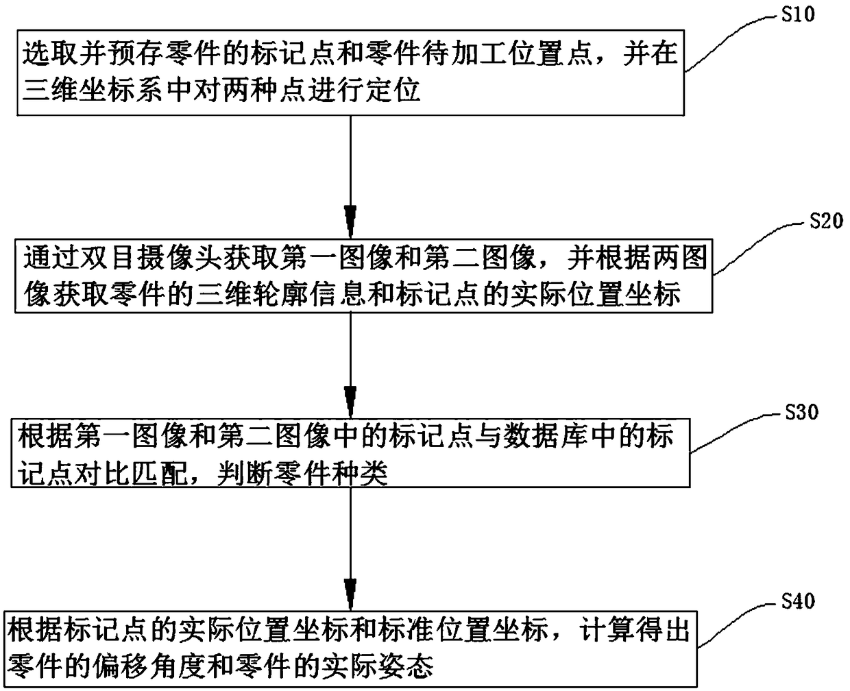
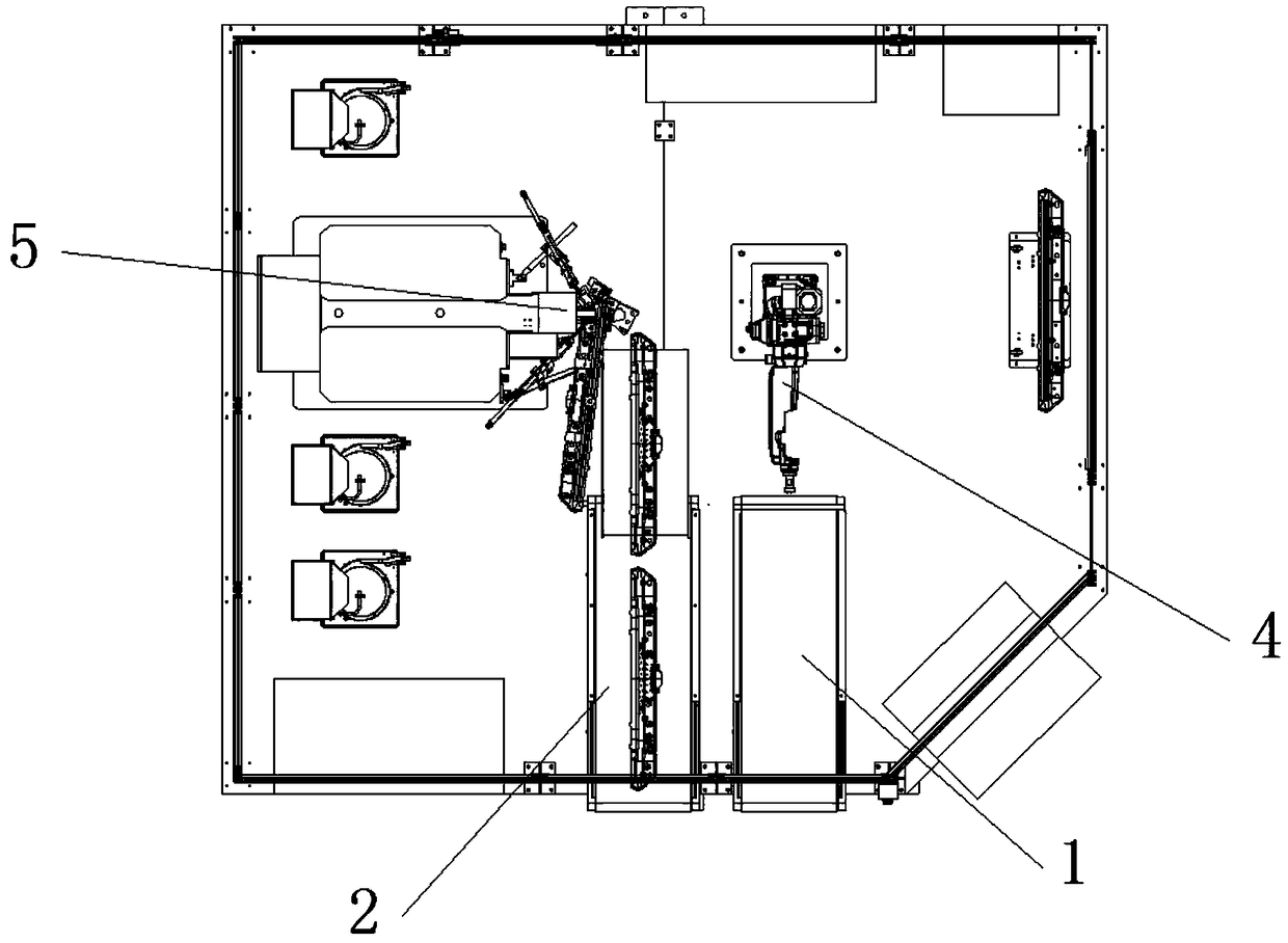
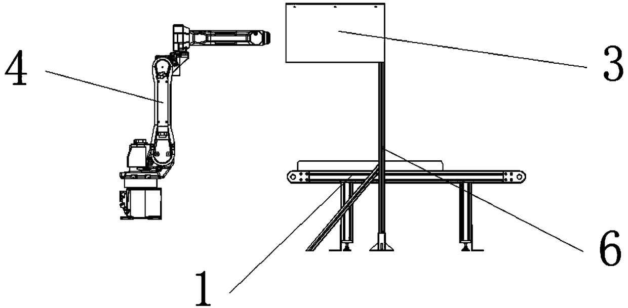
The invention provides a dual-purpose part identification method and device and a production line using the same. Part information is pre-stored; two images of the part at the same position are captured through a binocular camera; the part type and the posture of the part actually in a production line are identified according to identification points on the image; calculation is carried out according to the obtained part posture to obtain an actual position and posture of a to-be-processed position of the part so as to bring convenience for a control unit to adjust the angle of a manipulator picking the part; under the premise of ensuring the production quality, the labor capacity of workers is reduced, and the investment in the production line is reduced.

Description

Technical field [0001] The invention belongs to the field of visual recognition, and in particular relates to a visual grasping device and a recognition method thereof. Background technique [0002] In car body production, it is often necessary to weld some sheet metal parts. Now the sheet metal parts are usually placed on the conveyor belt, and the nuts are welded to the predetermined positions on the sheet metal through the nut conveyor. However, in actual production, in order to make the nuts The installation is accurate. It is necessary to classify the sheet metal parts according to the shape, and then place them on the conveying equipment according to a certain angle. After reaching the designated station, the nut is welded to the predetermined position by the manipulator. However, this increases the workload of the workers. Moreover, due to the difference in the shape of the sheet metal parts during the nut welding process, multiple production lines are often required to pr...

Claims


Application Information

Patent Timeline
Patent Type & Authority Applications(China)
IPC IPC(8): G01B11/00G01B11/26
CPCG01B11/002G01B11/26
Inventor 薛连凯
Owner 天津玛特智能科技有限公司
Why Eureka
Eureka Blog
Learn More