3D scanning imaging system for unmanned aerial vehicle

A scanning imaging, unmanned aerial vehicle technology, applied in radio wave measurement system, use of re-radiation, measurement device and other directions, can solve the problems of high use cost, single detection method, inability to extract depth and far-view information, etc., to prevent information Lost, improve the efficiency of use, improve the effect of work efficiency

Inactive Publication Date: 2019-01-11
苏州竹原信息科技有限公司
View PDF6 Cites 2 Cited by
  • Summary
  • Abstract
  • Description
  • Claims
  • Application Information

AI Technical Summary

Problems solved by technology

Therefore, there are the following problems: 1. The existing fixed-wing unmanned aerial vehicle power inspection system only uses visible light images and videos to inspect the corridors of transmission lines, and the detection method is single. parameters such as the distance between objects (vegetation), transmission line sag, and transmission line wind deflection cannot be measured.
2. Use a manned helicopter to carry a 3D laser scanner to inspect the transmission line, which is expensive to use and is not conducive to the promotion and use in actual production
[0004] However, the 3D laser scanner in this scheme has limited ability to obtain 3D visual information of captured objects. For example, it can extract approximate depth information about objects within the captured range, but cannot obtain detailed geometric information about the surfaces of these objects; or it can estimate Capture the distance of objects within the range, but cannot accurately generate the 3D shape of the object; or can obtain and generate detailed information on the surface of the object within the capture range, but cannot extract depth and far-view information

Method used


Image

  • 3D scanning imaging system for unmanned aerial vehicle
  • 3D scanning imaging system for unmanned aerial vehicle

Examples


Embodiment Construction

[0036] The present invention will be described in further detail below in conjunction with the accompanying drawings.

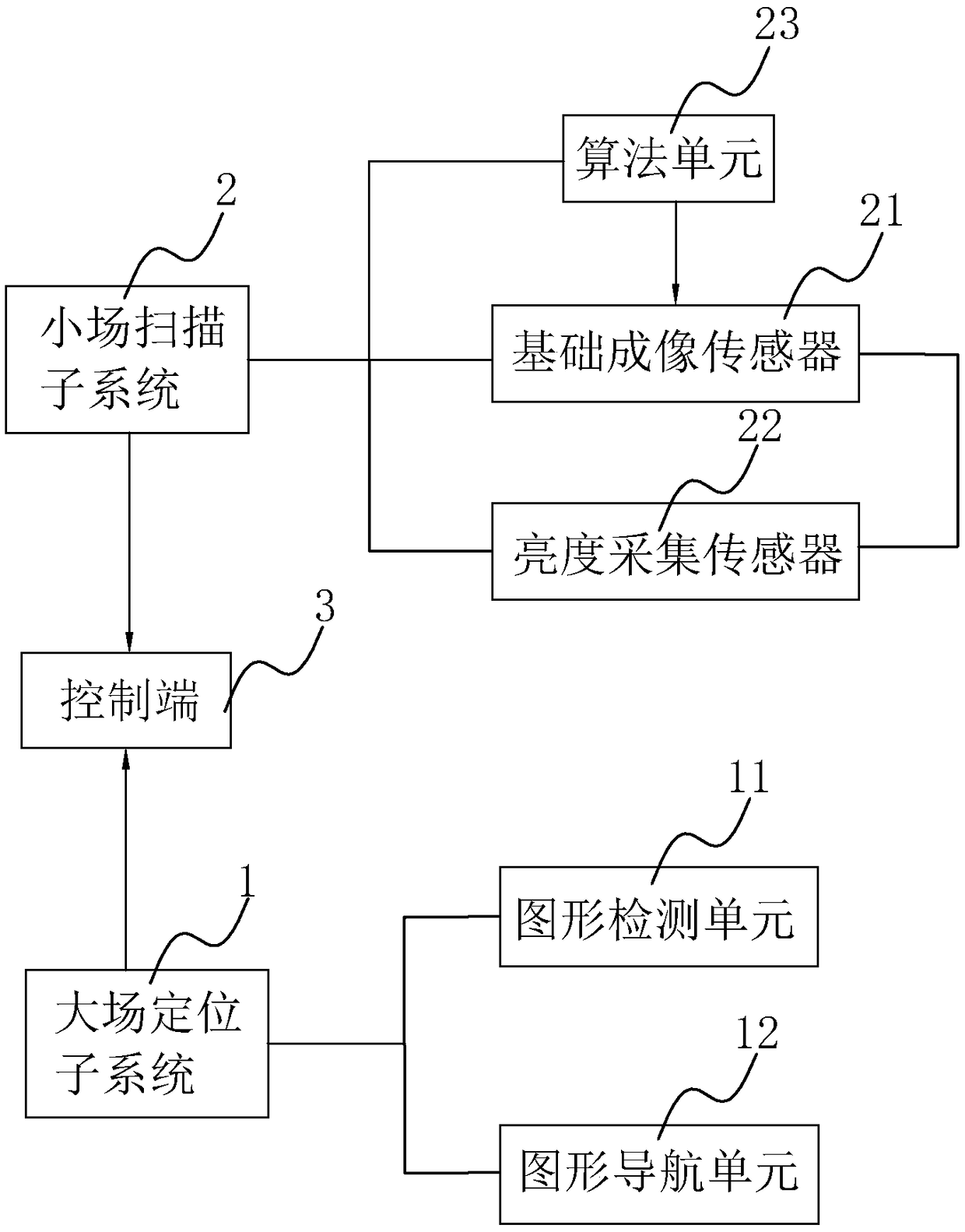
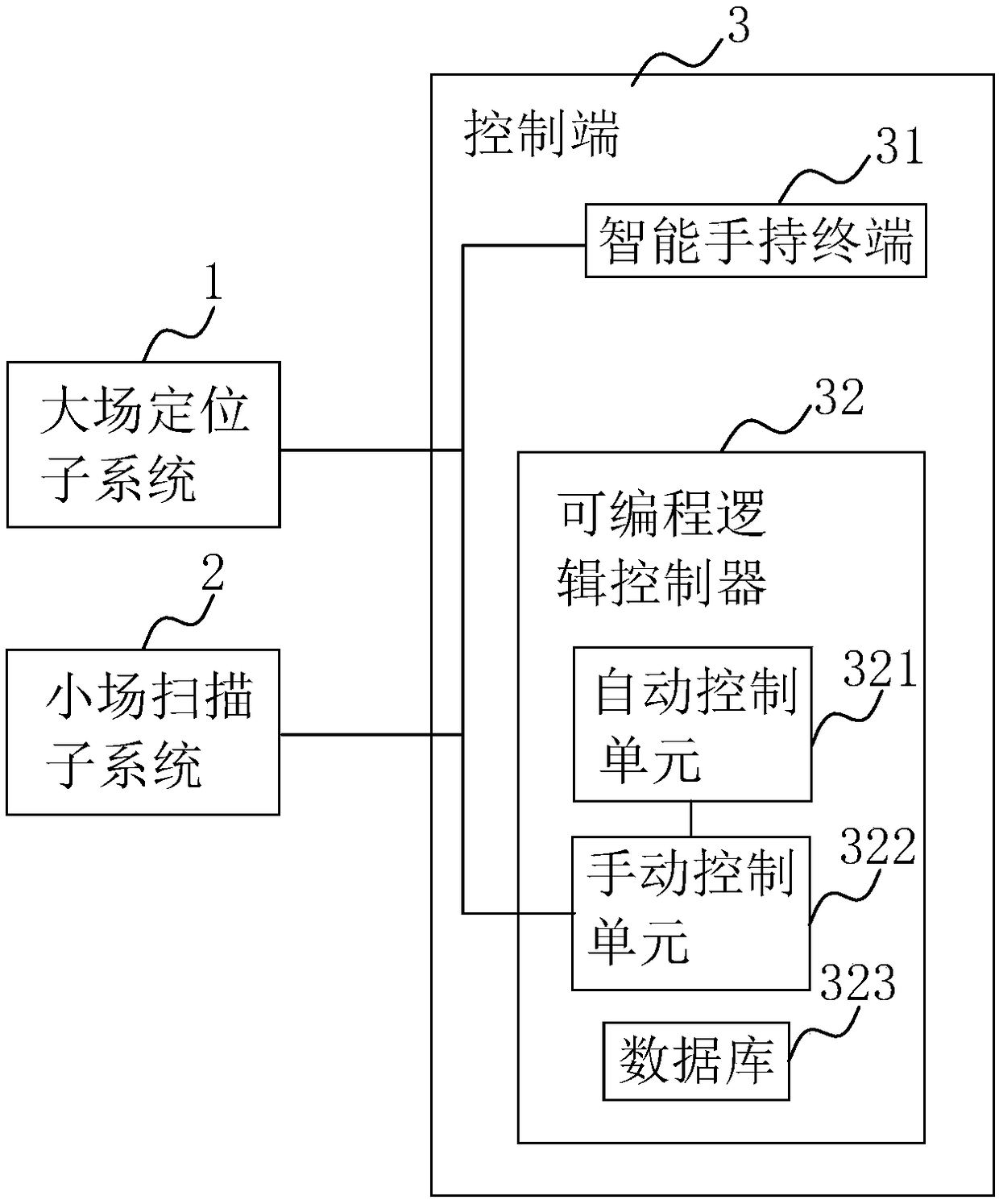
[0037] A drone 3D scanning imaging system, such as figure 1 As shown, it includes a large-field positioning subsystem 1, a small-field scanning subsystem 2 installed on the UAV, and a control terminal 3. The large-field positioning subsystem 1 and the small-field scanning subsystem collect the The data signal is sent to the control terminal 3, wherein the large-field positioning subsystem 1 can locate the UAV in real time, and the small-field scanning subsystem 2 can obtain the image parameter information of the scanned object, and then the two will collect the collected The data signal is transmitted to the control terminal 3 through the CAN bus for storage, scheduling, and processing. With the graphical and visual data display method as a reference, the specific location is located and scanned for imaging in the shortest time, improving the efficiency and e...


PUM


Abstract

The invention discloses a 3D scanning imaging system for an unmanned aerial vehicle, relates to the technical field of unmanned aerial vehicle image collection, and aims to solve the problem that a three-dimensional laser scanner in the prior art has limited performance for catching 3D vision information of an object. According to the technical key point, the system comprises a large-field positioning sub-system and a small-field scanning sub-system which are arranged on an unmanned aerial vehicle, as well as a control end, wherein the large-field positioning sub-system and the small-field scanning sub-system are used for transmitting a data signal collected through a CAN bus to the control end; the small-field scanning sub-system comprises a group of basic imaging sensors and at least twogroups of brightness collection sensors; and the basic imaging sensors and the brightness collection sensors are connected with the control end. The 3D scanning imaging system can be used for positioning a specific position and imaging by scanning in a shortest time, so that three-dimensional images can be collected, the visual effect can be improved, and the use efficiency and application meansof unmanned aerial vehicles can be improved.

Description

technical field [0001] The invention relates to the technical field of UAV image acquisition, in particular to a 3D scanning imaging system for UAVs. Background technique [0002] Unmanned helicopters have many advantages such as flexible takeoff and landing, free hovering, etc. However, at this stage, the technology of large-payload unmanned helicopters in China is still immature, and foreign mature products are in a state of banning sales to China. Therefore, there are the following problems: 1. The existing fixed-wing unmanned aerial vehicle power inspection system only uses visible light images and videos to inspect the corridors of transmission lines, and the detection method is single. Parameters such as the distance between objects (vegetation), transmission line sag and transmission line wind deflection cannot be measured. 2. Using a manned helicopter to carry a 3D laser scanner to inspect the power transmission line, the cost of use is high, which is not conducive ...

Claims


Application Information

Patent Timeline
Patent Type & Authority Applications(China)
IPC IPC(8): G01C11/02G01S11/12
CPCG01C11/02G01S11/12
Inventor 曹诚浩
Owner 苏州竹原信息科技有限公司
Why Eureka
Try Eureka