
Optical fiber macro bending pressure sensor and measuring system thereof

A pressure sensor, optical fiber macrobending technology, applied in the direction of measuring force, measuring device, instrument, etc., can solve the problems of difficult popularization and application, high cost, low yield, etc., and achieves simple modulation and demodulation method, simple structure, signal The effect of less processing

Active Publication Date: 2019-01-11
HARBIN INST OF TECH SHENZHEN GRADUATE SCHOOL
View PDF18 Cites 4 Cited by
  • Summary
  • Abstract
  • Description
  • Claims
  • Application Information

AI Technical Summary

Problems solved by technology

At present, there are fiber grating pressure sensors, lever-type fiber grating pressure sensors, and all-fiber high-sensitivity pressure sensors, but fiber grating pressure sensors have temperature-pressure cross-sensitivity, and the measurement results are easily affected by temperature. The structure is complex, and the optical fiber Fabry-Perot interference pressure sensor also needs to be temperature compensated, and the cavity sealing process is strict, and the yield is low
All in all, these two types of optical fiber pressure sensors are complex in structure, high in cost, and expensive in modulation and demodulation equipment, making it difficult to achieve popularization and application

Method used


Image

  • Optical fiber macro bending pressure sensor and measuring system thereof
  • Optical fiber macro bending pressure sensor and measuring system thereof
  • Optical fiber macro bending pressure sensor and measuring system thereof

Examples


Embodiment Construction

[0027] The following will clearly and completely describe the technical solutions in the embodiments of the present invention with reference to the accompanying drawings in the embodiments of the present invention. Obviously, the described embodiments are only some, not all, embodiments of the present invention. Based on the embodiments of the present invention, all other embodiments obtained by persons of ordinary skill in the art without making creative efforts belong to the protection scope of the present invention.

[0028] The purpose of the present invention is to use the excellent characteristics of optical fiber macrobend sensing technology, adopt the combination structure of elastic diaphragm and optical fiber macrobend, and provide a kind of optical fiber with simple structure, easy processing, simple modulation and demodulation method, and low price. Macrobend pressure sensor and its measurement system.

[0029] In order to make the above objects, features and advan...


PUM


Abstract

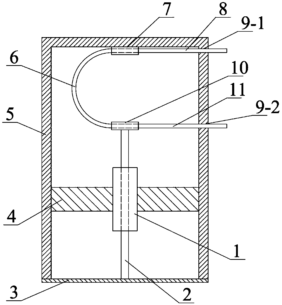
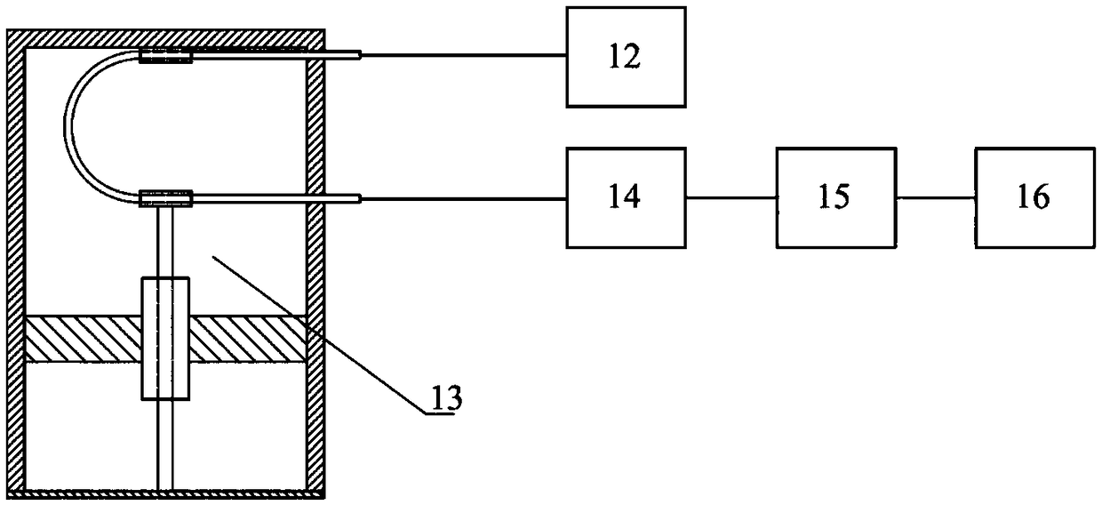
The invention discloses an optical fiber macro bending pressure sensor and a measuring system thereof. The optical fiber macro bending pressure sensor comprises a shell, an elastic diaphragm, a bracket, a sleeve, a dowel bar, an optical fiber, an incident optical fiber through hole and an emergent optical fiber through hole. The elastic diaphragm is fixedly arranged at the bottom of the shell, thebracket is fixedly arranged in the shell to fix the sleeve, and the incident optical fiber through hole is formed in the top of the shell; the dowel bar passes through the sleeve, one end of the dowel bar is fixed to the center of the elastic diaphragm, and the other end of the dowel bar is fixedly connected with the emergent optical fiber through hole; the optical fiber passes through the incident optical fiber through hole and the emergent optical fiber through hole to form a optical fiber macro bending section; and the sensor and the measuring system thereof adopt a combination structure of the elastic diaphragm and the optical fiber macro bending, and further adopt a photodiode which converts optical signals into electrical signals to realize pressure measurement. The optical fiber macro bending pressure sensor has the advantages of simple structure, easy processing, low price, intrinsic safety and corrosion resistance, and has wide application prospect in the fields of petrochemical industry, civil engineering, water conservancy, aerospace and the like.

Description

technical field [0001] The invention relates to the technical field of pressure sensors and optical fiber sensing, in particular to an optical fiber macrobending pressure sensor and a measurement system thereof. Background technique [0002] Optical fiber sensor is a sensing technology developed rapidly along with the development of optical fiber communication technology. It has the advantages of small size, light weight, high sensitivity, intrinsic safety, anti-electromagnetic interference, corrosion resistance, and long life. Through appropriate modulation and demodulation methods, fiber optic sensors can realize the measurement and long-term online monitoring of multiple physical quantities and parameters such as temperature, pressure, strain, acceleration, displacement, flow, electric field, magnetic field, etc., and thus have been widely researched and applied. [0003] In harsh environments such as high temperature, high pressure, corrosion, flammability, explosion, an...

Claims


Application Information

Patent Timeline
Patent Type & Authority Applications(China)
IPC IPC(8): G01L1/24
CPCG01L1/242
Inventor 李伟杰刘铁军邹笃建周傲高莎莎程汉斌
Owner HARBIN INST OF TECH SHENZHEN GRADUATE SCHOOL
Learn More