A magnetic rod self-rotating permanent magnet filter device

A filter device and magnetic bar technology, applied in the directions of magnetic separation, solid separation, cleaning methods and utensils, etc., can solve the problems of inability to achieve decontamination and filtering effect, deformation or damage of magnetic bars, complex power system, etc., and reduce the overall size of the equipment. Size, prevent easy deformation and wear, and avoid the effect of failure

Active Publication Date: 2019-08-13
WUHAN UNIV OF SCI & TECH
View PDF13 Cites 0 Cited by
  • Summary
  • Abstract
  • Description
  • Claims
  • Application Information

AI Technical Summary

Problems solved by technology

However, further studies have shown that no matter which type is mentioned above, there is a defect that the rigid contact between the decontamination mechanism and the magnetic rod is easy to cause deformation or damage to the magnetic rod, and it is impossible to achieve an efficient and satisfactory decontamination filtering effect; in addition, the current To achieve a complete decontamination operation, state-of-the-art coolant magnetic filter devices use a relatively independent power system to drive the magnetic bar to move linearly along the length direction, or to drive the scraper arm with a length equal to the magnetic bar to move linearly. It determines that the structural size of this type of equipment is too large, and the power system is complicated, which in turn affects the performance of the filtration efficiency.

Method used


Image

  • A magnetic rod self-rotating permanent magnet filter device
  • A magnetic rod self-rotating permanent magnet filter device
  • A magnetic rod self-rotating permanent magnet filter device

Examples


Embodiment Construction

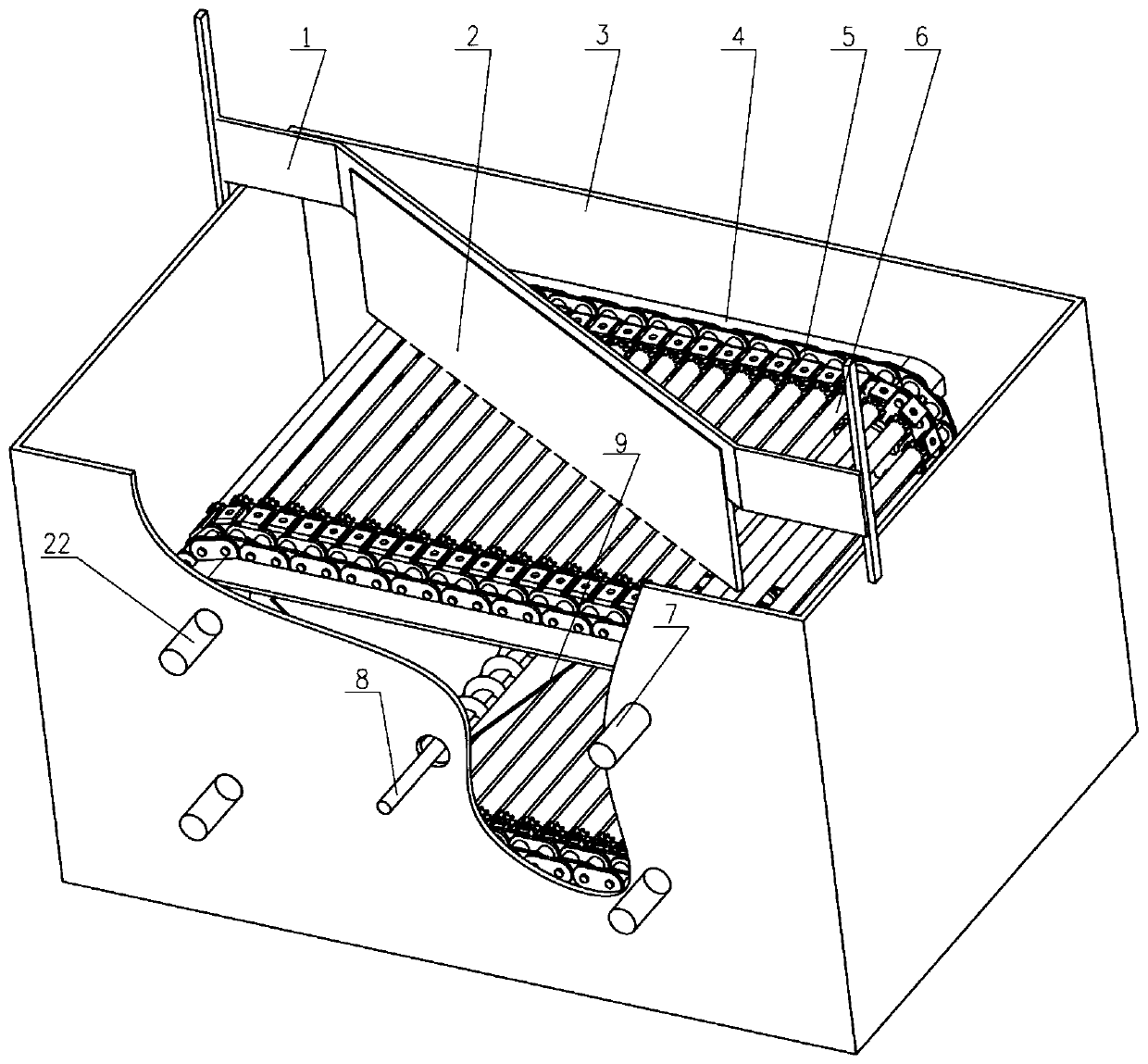
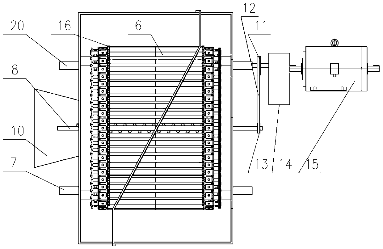
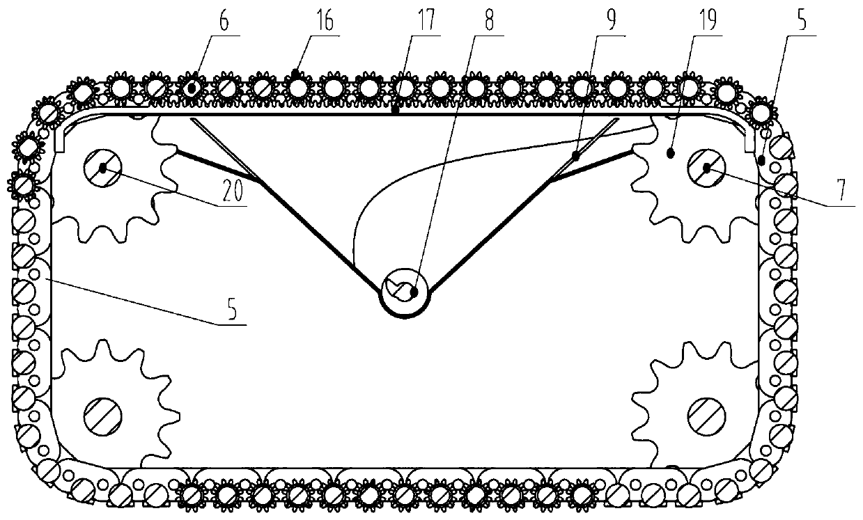
[0033] Such as Figure 1-3 It is one of the specific implementations of the magnet rod self-rotating permanent magnet filter device implemented according to the present invention.

[0034] Such as figure 1 and 2 According to the magnetic bar rotation type permanent magnet filtering device implemented in the present invention, waste water containing iron slag is housed in a water tank 3, and the magnetic chain formed by the chain 5 and the magnetic bar 6 connected in series is supported in the box by the supporting plate 4 and can Go round and round; outside the water tank 3, the motor 15 drives the magnetic chain to rotate through the reduction box 14;

[0035] The slag scraping brush 2 is arranged on the upper part of the magnetic chain through the support 1, and the slag scraping brush 2 is arranged perpendicular to the plane where the magnetic chain is located or at an angle, so that the slag scraping brush 2 can remove the slag body on the magnetic chain at the contact p...


PUM


Abstract

A magnetic bar self-rotation type permanent magnet filter is disclosed. A magnetic chain is driven by a motor drive mechanism to periodically reciprocate and to enter the liquid in a tank body used for storing cold rolling cooling liquid so that metal dust in the cooling liquid is adsorbed. A decontamination mechanism is disposed on the magnetic chain mechanism and is in contact with a decontamination segment, above the liquid level, of the reciprocating magnetic chain in a manner that the decontamination mechanism and the plane where the upper surface of the magnetic chain is are perpendicular to each other or arranged with a certain included angle, and in this process, each magnetic bar moves in a direction perpendicular to the length direction of the magnetic bar and rotates itself at the same time to scrape metal dust off the magnetic bar. Magnetic bar deformation or damage caused by rigid contact with the decontamination mechanism in a magnetic bar movement process, and device failure breakdown caused when the decontamination mechanism is stuck in the magnetic bar transmission chain can be prevented. In addition, the overall size of the device can be greatly reduced, the operation speed and follow-up effect of the magnetic chain mechanism are significantly improved, and the device has wider applicability.

Description

technical field [0001] The invention relates to a filter device, in particular to a filter device used for cold rolling cooling liquid treatment. Background technique [0002] The magnetic rod filter is the most widely used permanent magnet magnetic filter device at present. It is mainly used to remove iron powder in the liquid and keep the liquid clean to a certain extent. The permanent magnetic bar filter is a magnetic bar using high-performance permanent magnets as the magnetic source. A strong magnetic field is formed through a chain drive system to form a magnetic grid, which absorbs iron powder and other particles in the liquid, and then uses mechanical decontamination to remove the sticky particles. The iron powder attached to the magnetic rod is scraped off to make the magnetic rod clean before the next round of adsorption and decontamination. [0003] Studies have shown that compared with electromagnetic filters, permanent magnetic rod filters have the advantages o...

Claims


Application Information

Patent Timeline
Patent Type & Authority Patents(China)
IPC IPC(8): B03C1/02B08B1/02
CPCB03C1/02B08B1/005B08B1/02
Inventor 赵刚吴犇高星陈君文谢敏超曹昆仑付争伟
Owner WUHAN UNIV OF SCI & TECH
Why Eureka
Try Eureka