Rotary valve with improved structure

A technology of structural improvement and rotary valve, applied in the direction of sliding valve, valve device, engine components, etc., can solve the problems of reduced sealing performance of rotary valve rotary plate and upper reverse hanging plate, environmental pollution, easy wear, etc., to improve the efficiency of exhaust gas treatment and exhaust gas treatment quality, avoid environmental pollution, and ensure the effect of sealing

Pending Publication Date: 2018-08-17
KUNSHAN JUHONG MACHINERY TECH
View PDF0 Cites 0 Cited by
  • Summary
  • Abstract
  • Description
  • Claims
  • Application Information

AI Technical Summary

Problems solved by technology

The turntable of the rotary valve rotates every few seconds to realize the conversion between different areas of the rotary valve. At present, the rotary valve turntable of the rotary valve is in direct contact with the upper anti-hanging plate to realize the flow of exhaust gas between the two devices. After long-term use, The contact surface between the rotary valve turntable and the upper anti-suspension plate is easy to wear and deform, resulting in reduced sealing between the rotary valve turntable and the upper anti-suspension plate, air leakage, and environmental pollution

Method used


Image

  • Rotary valve with improved structure
  • Rotary valve with improved structure

Examples


Embodiment

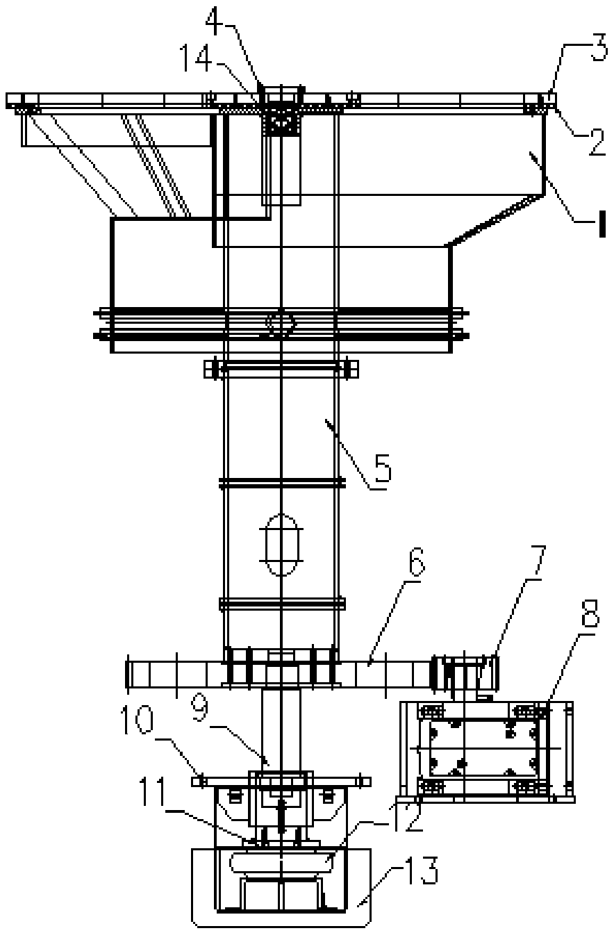
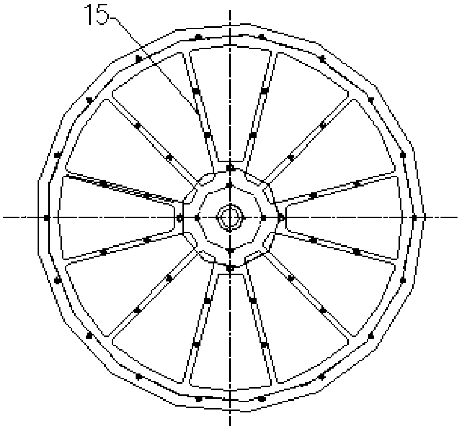
[0016] Embodiment: A rotary valve with improved structure, including rotary valve turntable 1, upper anti-hanging plate 3 and wear-resistant plate 2, the wear-resistant plate 2 made of wear-resistant material can be detachably fixed and installed on the upper anti-hanging On the surface of one end of the disk 3, the surface of the rotary valve turntable 1 can rotate against the surface of the wear-resistant plate 2, and the wear-resistant plate 2 is installed on the lower end of the upper anti-suspension plate 3, and then the rotary valve turntable 1 is pressed against the wear-resistant plate 2 , the rotary valve turntable 1 is in contact with the wear-resistant plate 2 when rotating, and the wear-resistant plate 2 is made of wear-resistant material, which is not easy to wear after long-term use, and can ensure the sealing between the rotary valve turntable 1 and the upper anti-hanging plate 3, When the wear-resistant plate 2 is worn out, it can be quickly replaced with a new ...


PUM


Abstract

The invention discloses a rotary valve with an improved structure. The rotary valve comprises a rotary valve rotating disc, an upper reverse-hanging disc and an abrasion-resistant plate. The abrasion-resistant plate made of an abrasion-resistant material is detachably and fixedly mounted on the surface of one end of the upper reverse-hanging disc, and the surface of the rotary valve rotating disccan rotatably and tightly abut against the surface of the abrasion-resistant plate. According to the rotary valve with the improved structure, the abrasion-resistant plate is mounted on the upper reverse-hanging disc, the rotary valve rotating disc and the abrasion-resistant plate make close contact, and relative rotating friction occurs between the rotary valve rotating disc and the abrasion-resistant plate, so that the abrasion-resistant plate is not liable to be abraded and deform after being used for a long term, airtightness in the waste gas circulating process is guaranteed, and environment pollution is avoided; and automatic rotating of the rotary valve rotating disc is further achieved by arranging a motor decelerator and a rotary valve supporting column, the distance between the rotary valve rotating disc and the upper reverse hanging disc is adjusted by arranging an airbag, repair and maintenance are facilitated while the airtightness is further improved, the waste treatmentefficiency and quality are greatly improved, and the service life of the equipment is prolonged.

Description

technical field [0001] The invention relates to a rotary valve, especially a rotary valve with improved structure. Background technique [0002] During the exhaust gas treatment process, the exhaust gas enters the ceramic heat recovery area through the rotary valve flow channel, then enters the ceramic oxidation area from the combustion chamber, and finally exits the chimney from the bottom of the furnace. The turntable of the rotary valve rotates every few seconds to realize the conversion between different areas of the rotary valve. At present, the rotary valve turntable of the rotary valve is in direct contact with the upper anti-hanging plate to realize the flow of exhaust gas between the two devices. After long-term use, The contact surface between the rotary valve turntable and the upper anti-suspension plate is easy to wear and deform, resulting in reduced sealing between the rotary valve turntable and the upper anti-suspension plate, air leakage, and environmental po...

Claims


Application Information

Patent Timeline
Patent Type & Authority Applications(China)
IPC IPC(8): F16K3/08F16K3/30F16K3/314
CPCF16K3/08F16K3/30F16K3/314
Inventor 施元中
Owner KUNSHAN JUHONG MACHINERY TECH
Why Eureka
Try Eureka