Dense hole punching mold and punching method

A dense hole and mold technology, applied in cleaning methods and utensils, chemical instruments and methods, manufacturing tools, etc., can solve problems such as inability to meet mass production, chemical waste polluting the environment, low production efficiency, etc., to achieve visual experience guarantee, material The effect of high utilization rate and high production efficiency

Inactive Publication Date: 2019-01-15
QINGDAO HAIER MOLDS
View PDF7 Cites 0 Cited by
  • Summary
  • Abstract
  • Description
  • Claims
  • Application Information

AI Technical Summary

Problems solved by technology

[0002] In the prior art, most of the realization methods for processing dense holes are chemical corrosion. By making a chemical model, the chemical liquid reacts with the thin plate metal, and the metal dissolves in the acidic liquid, thereby forming small holes one by one. However, this method The production efficiency is low, which cannot meet mass production, and the chemical waste produced will pollute the environment. If the product has appearance requirements, the metal sheet is often covered with a film, which cannot be achieved by chemical corrosion again.
[0003] Another method is to use laser laser processing, put the metal sheet on the laser table, the laser head emits a high-energy beam, the beam is perpendicular to the sheet, instantly generates high temperature at the irradiation point, and liquefies in the small metal hole. After cooling, The small metal sheet in the round hole is separated from the surrounding of the hole to realize the small hole, but there is a defect in the production of this method. There are small particles after melting and cooling around the small hole, which is not smooth to the touch by hand and has black edges on the outside. Affect the appearance

Method used


Image

  • Dense hole punching mold and punching method
  • Dense hole punching mold and punching method
  • Dense hole punching mold and punching method

Examples


Embodiment Construction

[0037] Below in conjunction with accompanying drawing and specific embodiment the present invention is described in further detail:

[0038] In order to make the object, technical solution and advantages of the present invention clearer, the present invention will be further described in detail below in conjunction with the accompanying drawings and embodiments. It should be understood that the specific embodiments described here are only used to explain the present invention, not to limit the present invention.

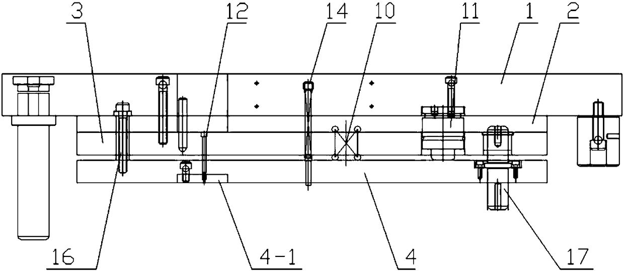
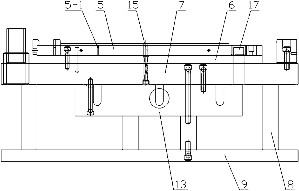
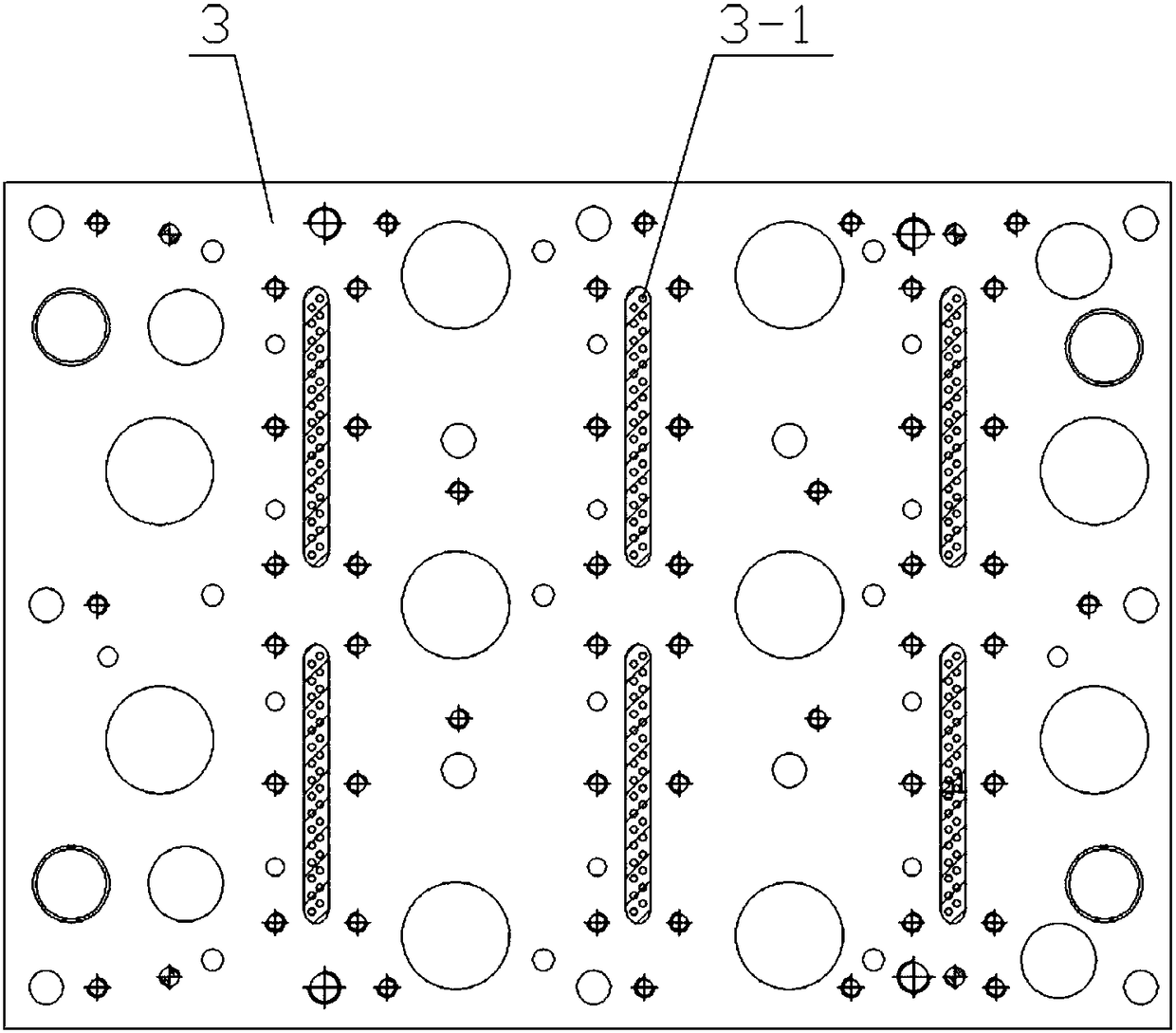
[0039] Such as Figure 1 to Figure 9 As shown, a dense hole blanking die according to the present invention mainly includes an upper mold and a lower mold. , The lower mold mainly includes a lower template 5, a lower backing plate 6, a lower mold base 7, a plurality of lower mold legs 8, and a lower supporting plate 9.

[0040] The upper mold from top to bottom is the upper mold base 1, the upper backing plate 2, the upper splint 3, and the upper stripping plate 4,...


PUM


Abstract

The invention relates to a dense hole punching mold and a punching method. The mold comprise an upper mold and a lower mold, wherein the lower mold comprises a lower mold plate used for containing a to-be-machined product, the upper mold comprises an upper mold base, an upper stripper plate and a punch, wherein the upper stripper plate and the punch are arranged below the upper mold base; and an upper stripper plate insert is arranged on the upper stripper plate, a stepped hole which an blade end of the punch penetrates through is formed in the upper stripper plate insert, the blade end of thepunch penetrates out of the stepped hole, and a rod part is left in the upper stripper plate insert. According to the method, the metal sheet with the different sizes of the dense holes can be machined, and no surface coating limitation exists; when the dense hole of the metal sheet has the appearance requirement, the dense hole machined by the mold is small in burr and free of black edges, the flatness of the whole piece is good, the hole distance and the hole diameter are small, and the visual feeling after hand feeling and illumination can be guaranteed; and in addition, the dense hole machining is realized by blanking of the mold, the mold and the method have the advantages of being high in a material utilization rate, high in production efficiency, environmentally friendly, and freeof pollution.

Description

technical field [0001] The invention relates to a die, in particular to a dense hole punching die and a punching method. Background technique [0002] In the prior art, most of the realization methods for processing dense holes are chemical corrosion. By making a chemical model, the chemical liquid reacts with the thin plate metal, and the metal dissolves in the acidic liquid, thereby forming small holes one by one. However, this method The production efficiency is low, which cannot meet mass production, and the chemical waste produced will pollute the environment. If the product has appearance requirements, the metal sheet is often covered with a film, which cannot be achieved by chemical corrosion again. [0003] Another method is to use laser laser processing, put the metal sheet on the laser table, the laser head emits a high-energy beam, the beam is perpendicular to the sheet, instantly generates high temperature at the irradiation point, and liquefies in the small meta...

Claims


Application Information

Patent Timeline
Patent Type & Authority Applications(China)
IPC IPC(8): B21D28/14B21D25/04B21D45/06B08B15/04
CPCB21D28/14B08B15/04B21D28/04B21D45/006B21D45/06
Inventor 刘国荣米永东齐哲赵朋唐军波
Owner QINGDAO HAIER MOLDS
Why Eureka
Try Eureka