Supercharge Your Innovation With Domain-Expert AI Agents!

A linear friction welding method

A linear friction welding, friction plate technology, applied in welding equipment, non-electric welding equipment, metal processing equipment, etc., can solve the problems that the zero return accuracy cannot meet the technical requirements of the product, the valve port is large, and the cost is high.

Active Publication Date: 2021-02-02
AVIC BEIJING AERONAUTICAL MFG TECH RES INST
View PDF7 Cites 0 Cited by
  • Summary
  • Abstract
  • Description
  • Claims
  • Application Information

AI Technical Summary

Problems solved by technology

Take the linear friction welding equipment that can provide a maximum excitation force of 15 tons as an example. The commonly used vibration frequency is 50Hz, the amplitude is ~4mm, and the quality of the vibrator is 230kg. The excitation force required for high-frequency vibration is F=(2*3.14*f)^ 2 *A*m / 10^ 7 =(2*3.14*50)^ 2 *4*230 / 10^ 7 =9 tons, that is to say, most of the power is consumed by high-frequency vibration, and the energy utilization rate is low
[0008] (2) Poor welding accuracy;
[0009] During welding, the high-frequency vibration requires a large flow of pressure oil, so a large-flow servo valve must be selected, but the valve with a larger flow rate has a larger valve port, and it is very difficult to precisely control the flow through the valve port, resulting in welding The alignment accuracy of the parts in the direction of vibration is poor
Taking the medium-sized linear friction welding equipment as an example, its zero return error is at most ±0.35mm. For high-precision products, such zero return accuracy cannot meet the product technical requirements
[0010] (3) The cost of the hydraulic system of the equipment is high
[0011] Conventional linear friction welding equipment usually uses a set of large-scale high-power hydraulic system to realize the high-frequency vibration of the vibrating slide table and the upsetting movement of the upsetting fixture. The hydraulic system is complicated and the cost is high.

Method used


Image

  • A linear friction welding method
  • A linear friction welding method
  • A linear friction welding method

Examples


Embodiment 1

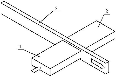
[0034] figure 1 A schematic structural view of an embodiment of a linear friction welding method of the present invention is shown. The first weldment 1 and the second weldment 2 and the friction plate 3 are carried out according to the method. Since there is no equipment to test this method, only ANSYS software can be used for numerical simulation. The model material is set to TC4, and the friction upsetting force is 10000kg , the moving speed of the friction piece is set to 500mm / s.

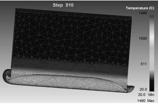
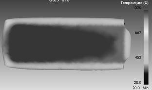
[0035] Such as figure 2 As shown, the flash is extruded on the contact surface of the first weldment 1 and the second weldment 2, and the flash in the unidirectional friction welding process is similar to the linear friction welding, the difference is that at the front end of the friction plate 3 in the forward direction, the flash The edge is small, while the rear end of the friction plate 3 in the advancing direction is larger and curled. There is no ripple mark on the flash edges of the ...


PUM


Abstract

The invention discloses a linear friction welding method, which relates to the field of welding methods. The friction plate moves at a high speed, the friction plate rubs against the first weldment and the second weldment to generate heat, and the material at the contact surface softens; the friction plate is pulled out Finally, the first weldment and the second weldment are brought into contact together under the drive of the upsetting force, and the materials at the contact surface of the first weldment and the second weldment are combined into one body through diffusion. Compared with conventional linear friction welding, the technical solution of the present invention requires less energy consumption, lower equipment cost, significantly reduces process cost, and has no vibration, and accurate positioning is easy to achieve, thereby achieving higher welding accuracy.

Description

technical field [0001] The invention relates to the field of welding methods, in particular to a linear friction welding method. Background technique [0002] Linear friction welding (Linear Friction Welding) is a welding method that has developed rapidly in recent years. It is mainly used in the manufacture of engine blisks and aircraft frame beam parts. The weldment 2 is clamped in the fixture of the vibrating slide table in the vertical High-frequency vibration in the direction, the common vibration frequency is 50Hz; the weldment 1 is installed in the fixture of the workbench, and under the action of the upsetting force in the horizontal direction, it contacts the end surface of the weldment 2, and high-frequency friction occurs on the contact surface of the two workpieces Heat is generated. As the temperature rises, the material on the contact surface softens and deforms. When the deformation reaches a certain level, the vibration is stopped quickly to ensure that the u...

Claims


Application Information

Patent Timeline
Patent Type & Authority Patents(China)
IPC IPC(8): B23K20/12
CPCB23K20/122
Inventor 李辉张田仓金俊龙季亚娟
Owner AVIC BEIJING AERONAUTICAL MFG TECH RES INST
Features
  • R&D
  • Intellectual Property
  • Life Sciences
  • Materials
  • Tech Scout
  • Unparalleled Data Quality
  • Higher Quality Content
  • 60% Fewer Hallucinations
Learn More