
Reducer shell polishing equipment with robot

A reducer and robot technology, which is applied in the direction of grinding/polishing equipment, metal processing equipment, grinding machine parts, etc., can solve the harsh environment of workers' processing, cannot meet the needs of production and processing, and cannot achieve the follow-up of strength Multi-angle and other issues, to achieve the effect of improving grinding accuracy and finished product quality, reducing labor costs and error rates, and improving grinding efficiency and precision

Pending Publication Date: 2019-01-15
GUANGDONG LXD ROBOTICS CO LTD
View PDF0 Cites 8 Cited by
  • Summary
  • Abstract
  • Description
  • Claims
  • Application Information

AI Technical Summary

Problems solved by technology

[0002] At present, most of the reducer shells in the industry still use the traditional manual grinding method. Since the grinding process is done manually in this way, its stability is poor. Due to different personal techniques, the uniformity of grinding is not consistent, and it is easy to make mistakes. The quality of the polished finished product is poor and inconsistent. At the same time, the processing efficiency is slow, the workload is heavy, the production cost is high, and the processing environment of the workers is harsh, which is likely to cause physical and mental damage to the workers. The manufacturer must also consider the processing environment of the workers and the safety of the workers. At the same time, there are very few workers engaged in this kind of grinding work, it is difficult for manufacturers to recruit workers, and the cost of employment is gradually increasing, which can no longer meet the needs of modern production and processing.
For this reason, relevant technical personnel have developed grinding equipment specially used for the reducer shell, but these grinding equipment cannot achieve the controllability of the force and the multi-angle of grinding, but the quality of the finished product is poor, and it cannot meet the requirements of production and processing. need

Method used


Image

  • Reducer shell polishing equipment with robot
  • Reducer shell polishing equipment with robot
  • Reducer shell polishing equipment with robot

Examples


Embodiment Construction

[0025] The present invention will be further described below in conjunction with the accompanying drawings and embodiments.

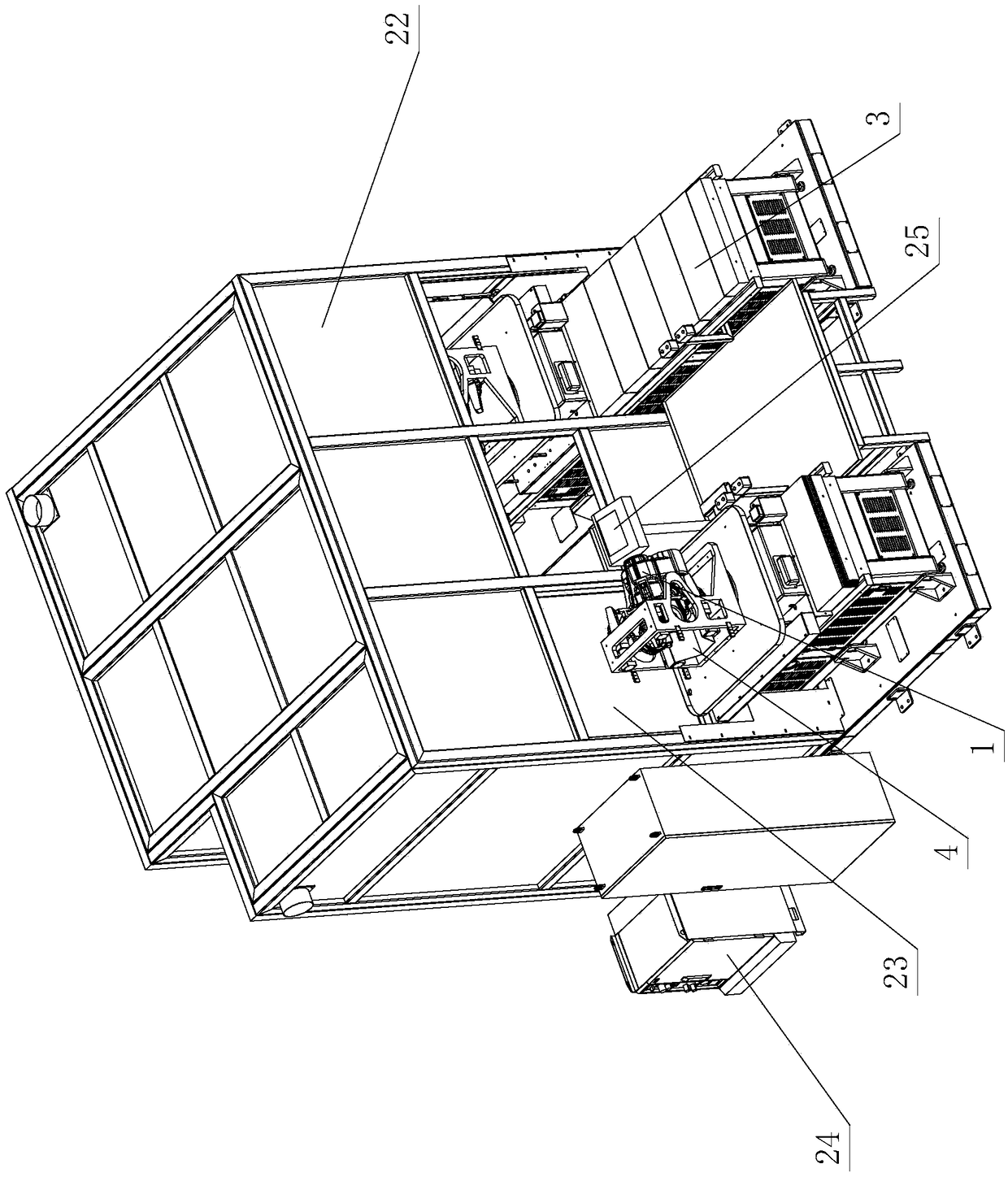
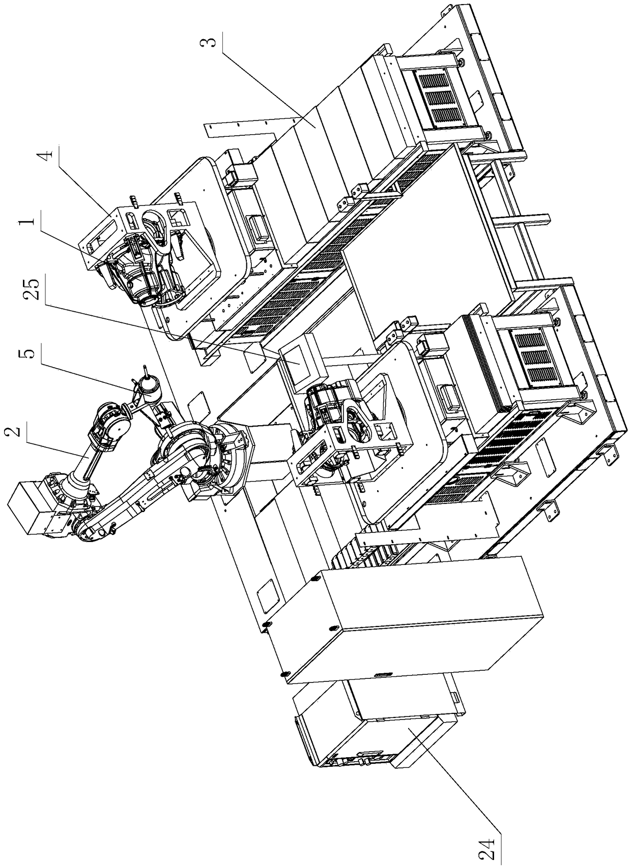
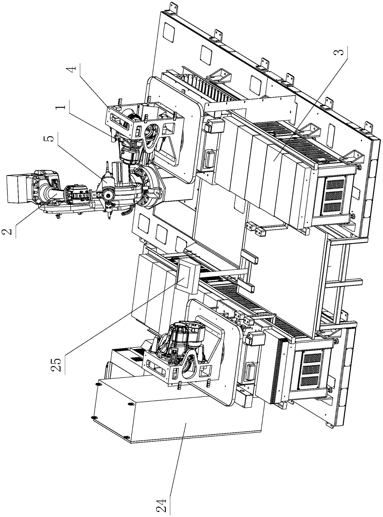
[0026] see figure 1 - Figure 7 , the reducer shell grinding equipment with a robot, including a workpiece to be polished 1, a six-axis robot 2 and a loading and unloading delivery platform 3, is characterized in that: there are two loading and unloading delivery platforms 3, and the two loading and unloading delivery platforms 3 A clamp assembly 4 is respectively provided, and the clamp assembly 4 slides back and forth on the loading and unloading conveying platform 3, and forms a loading and unloading station and a grinding station; the six-axis robot 2 is arranged between two loading and unloading conveying platforms 3, And there are three rotating and floating grinding assemblies 5 arranged on it; the workpiece 1 to be polished is fed to the clamp assembly 4 through the loading and unloading station, and slides to the grinding station through the c...


PUM


Abstract

Reducer shell polishing equipment with a robot comprises a piece to be polished, the six-axis robot and two feeding and discharging conveying platforms. The two feeding and discharging conveying platforms are provided with fixture assemblies. The fixture assemblies slide back and forth on the feeding and discharging conveying platforms, and a feeding and discharging station and a polishing stationare formed. The six-axis robot is arranged between the two feeding and discharging conveying platforms and is provided with three rotary floating polishing assemblies. The piece to be polished is fedto the fixture assemblies through the feeding and discharging station and slides to the polishing station through the fixture assemblies. The six-axis robot carries out polishing machining on the piece to be polished through the three rotary floating polishing assemblies, and the polished and machined piece to be polished slides to the feeding and discharging station through the fixture assemblies and is discharged. By means of the improvement of the structure, the reducer shell polishing equipment with the robot has the advantages of being simple and reasonable in structure, stable in quality, safe, reliable, capable of achieving full-automatic production, high in production efficiency and the like and is high in practicality.

Description

technical field [0001] The invention relates to a reducer shell grinding equipment with a robot. Background technique [0002] At present, most of the reducer shells in the industry still use the traditional manual grinding method. Since the grinding process is done manually in this way, its stability is poor. Due to different personal techniques, the uniformity of grinding is not consistent, and it is easy to make mistakes. The quality of the polished finished product is poor and inconsistent. At the same time, the processing efficiency is slow, the workload is heavy, the production cost is high, and the processing environment of the workers is harsh, which is likely to cause physical and mental damage to the workers. The manufacturer must also consider the processing environment of the workers and the safety of the workers. At the same time, there are very few workers engaged in this kind of grinding work, it is difficult for manufacturers to recruit workers, and the cost ...

Claims


Application Information

Patent Timeline
Patent Type & Authority Applications(China)
IPC IPC(8): B24B19/00B24B27/02B24B41/00B24B41/06B24B27/00B24B55/06B24B55/04B25J11/00
CPCB24B19/00B24B27/0023B24B27/0076B24B27/02B24B41/005B24B41/06B24B55/04B24B55/06B25J11/0065
Inventor 朱觉荣蒋小双胡尕磊
Owner GUANGDONG LXD ROBOTICS CO LTD
Learn More