Force controllable gripper

A technology of mechanical claws and power sources, applied in the field of force-controlled mechanical claws, can solve problems such as unsuitable for grasping small precision parts, complex structure design and transmission mode, mechanical claws cannot control the grasping force, etc., and achieve reliable transmission pairs Design, compact structure, good gripping stability

Pending Publication Date: 2019-01-15
SHANGHAI JIAO TONG UNIV
View PDF0 Cites 6 Cited by
  • Summary
  • Abstract
  • Description
  • Claims
  • Application Information

AI Technical Summary

Problems solved by technology

[0008] In view of the above-mentioned defects of the prior art, the technical problem to be solved by the present invention is that the mechanical claw cannot control the grasping force, and the complex structure design and transmission mode lead to complicated control and bulky body, which is not suitable for grasping small precision parts

Method used


Image

  • Force controllable gripper
  • Force controllable gripper

Examples


Embodiment Construction

[0034] The following describes a preferred embodiment of the present invention with reference to the accompanying drawings to make its technical content clearer and easier to understand. The present invention can be embodied in many different forms of embodiments, and the protection scope of the present invention is not limited to the embodiments mentioned herein.

[0035] In the drawings, components with the same structure are denoted by the same numerals, and components with similar structures or functions are denoted by similar numerals. The size and thickness of each component shown in the drawings are shown arbitrarily, and the present invention does not limit the size and thickness of each component. In order to make the illustration clearer, the thickness of parts is appropriately exaggerated in some places in the drawings.

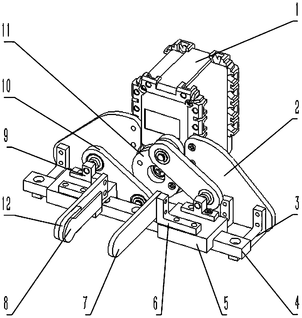
[0036] like figure 1 As shown, the force-controlled mechanical claw of this embodiment includes a steering gear 1, two main boards 2, four botto...


PUM


Abstract

The invention discloses a force controllable gripper, comprising a power source, two gripping ends for realizing single degree of freedom motion, a crank sliding block structure, a gripping force control module and a center surface; wherein the crank sliding block structure comprises a crank, a slide rail, two sliding structures, two connecting rods, two first rotating pairs and two second rotating pairs. The central plane is defined as a plane rotating through a crank and is perpendicular to a sliding plane. When the crank rotates, the two sliding structures are driven to slide and are alwayssymmetrical about the central plane. A gripping force control module is added on the gripping end to achieve flexible contact with a target object and gripping force detection. There is a simple conversion relationship between the displacement of the grip end, the contact force and the rotation angle of a power source and torque, which is convenient for designing the control algorithm. The forcecontrollable gripper realizes the gripping force control, can stably grip a target object, and is easy to control. The force controllable gripper is designed to be smaller and lighter, and is suitablefor scenes that require lightweight gripping.

Description

technical field [0001] The invention relates to the field of mechanical gripper equipment, in particular to a force-controlled mechanical gripper. Background technique [0002] With the rapid development of industrial automation, automatic control is almost everywhere, and mechanical grippers, as an important actuator in the control system, play a very important role in modern industrial production. Mechanical grippers can be divided into pneumatic, hydraulic and electric grippers according to their driving methods. According to their gripper types, they can be divided into 2-jaw type, 3-jaw type and multi-jaw type. According to their movement methods, they can be divided into translational type and rotary type. [0003] In existing mechanical claws, there are following defects: [0004] 1. Generally, only simple position control can be realized, lack of control on the grasping force, and cannot be applied to occasions that need to control the grasping force. For example, i...

Claims


Application Information

Patent Timeline
Patent Type & Authority Applications(China)
IPC IPC(8): B25J15/02B25J13/08B25J15/12
CPCB25J15/0206B25J13/085B25J15/12
Inventor 吴建华肖志键熊振华朱向阳
Owner SHANGHAI JIAO TONG UNIV
Why Eureka
Try Eureka