
Five roller moulding machine for composite floors

A composite floor and molding machine technology, applied in the application, household appliances, other household appliances, etc., can solve the problems of poor continuous production capacity of the production line, poor cooling effect of the four-roller, and the film is not easy to cover firmly, etc. Replacing the rollers, improving the molding effect and compounding effect, and the effect of humanized design

Pending Publication Date: 2019-01-15
常州金纬片板设备制造有限公司
View PDF0 Cites 0 Cited by
  • Summary
  • Abstract
  • Description
  • Claims
  • Application Information

AI Technical Summary

Problems solved by technology

The forming of the existing composite floor adopts a vertical four-roll structure. The floor base material, the printed film and the wear-resistant film are formed by pressing the upper two rolls. During the processing, the forming effect is poor, and the film is not easy to cover firmly. Not good, the output is low, the continuous production capacity of the production line is poor, and because the structure of the vertical four-roller is limited, the center height is high, and it is inconvenient to replace the rollers, resulting in unhumanized operation

Method used


Image

  • Five roller moulding machine for composite floors
  • Five roller moulding machine for composite floors

Examples


Embodiment Construction

[0023] In order to make the content of the present invention more clearly understood, the present invention will be further described in detail below based on specific embodiments and in conjunction with the accompanying drawings.

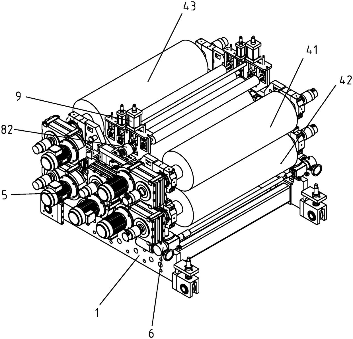
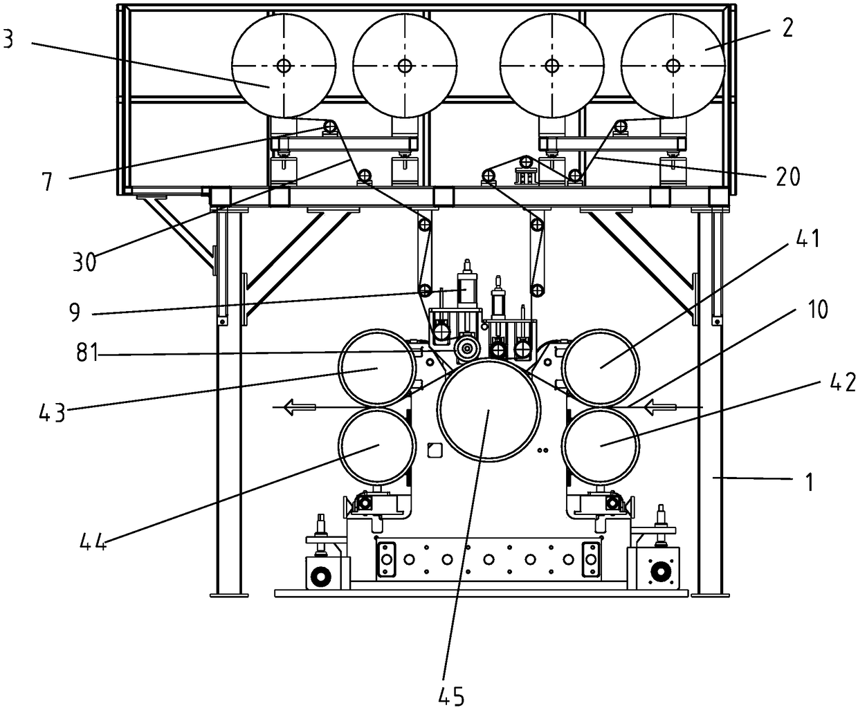
[0024] Such as figure 1 , 2 As shown, a five-roll forming machine for composite flooring includes:

[0025] Rack 1;

[0026] A printing film unwinding device 2 for supporting the printing film roll and unwinding the printing film roll;

[0027] A wear-resistant film unwinding device 3 for supporting the wear-resistant film roll and unwinding the wear-resistant film roll;

[0028] The front pair of rollers, the front pair of rollers include an upper forming roller 41 and a lower forming roller 42 that are parallel up and down and are rotatably supported on the frame 1 respectively, and a feed channel is formed between the upper forming roller 41 and the lower forming roller 42 ;

[0029] The rear pair of rollers, the rear pair of rollers includ...


PUM


Abstract

The invention discloses a five roller moulding machine for composite floors. The five roller moulding machine comprises a frame, a printed film unreeling device, a wear resistant film unreeling device, a pair of front rollers, a pair of rear rollers, a moulding cooling roller, and five rotation driving members. The front rollers are an upper moulding roller and a lower moulding roller, which are parallelly arranged in the vertical direction and rotatingly arranged on the frame. A feeding channel is formed between the upper moulding roller and the lower moulding roller. The rear rollers are a patterned roller and a shaded roller, which are parallelly arranged in the vertical direction and rotatingly arranged on the frame. A discharging channel is formed between the patterned roller and theshaded roller. The moulding cooling roller is rotatingly arranged on the frame and is between the feeding channel and the discharging channel so that a floor substrate can conveniently go through thefeeding channel, the moulding cooling channel and the discharging channel in sequence. A printed film, a wear resistant film, and a floor substrate are compounded on the outer surface of the mouldingcooling roller. The provided moulding machine improves the moulding effect and compound effect of composite floors, the quality of composite floors is guaranteed, the structure is reasonable, and theoperation is easy.

Description

technical field [0001] The invention relates to a five-roll molding machine for composite flooring. Background technique [0002] Composite flooring has been widely used in various places such as home decoration, hotels, and office buildings because of its appearance of ordinary wooden floors, good barrier properties, heat preservation, moisture resistance, and convenient construction. The forming of the existing composite floor adopts a vertical four-roll structure. The floor base material, the printed film and the wear-resistant film are formed by pressing the upper two rolls. During the processing, the forming effect is poor, and the film is not easy to cover firmly. Not good, the output is low, the continuous production capacity of the production line is poor, and because the structure of the vertical four-roller is limited, the center height is high, and it is inconvenient to replace the rollers, resulting in unhumanized operation. Contents of the invention [0003] ...

Claims


Application Information

Patent Timeline
Patent Type & Authority Applications(China)
IPC IPC(8): B29C65/56B29C65/78B29L9/00B29L7/00
CPCB29C65/565B29C65/7861B29C66/0242B29C66/0244B29C66/45B29C66/72329B29L2009/00B29L2007/002
Inventor 何海潮夏春生
Owner 常州金纬片板设备制造有限公司
Learn More