Single crystal silicon rod turnover device
A single-crystal silicon rod and rotator technology, which is applied to conveyor objects, furnaces, lighting and heating equipment, etc., can solve problems such as difficulty in moving silicon rods, and achieve the effects of reducing manual intervention, improving stability and reducing operating costs.
- Summary
- Abstract
- Description
- Claims
- Application Information
AI Technical Summary
Problems solved by technology
Method used
Image

Examples
Embodiment 1
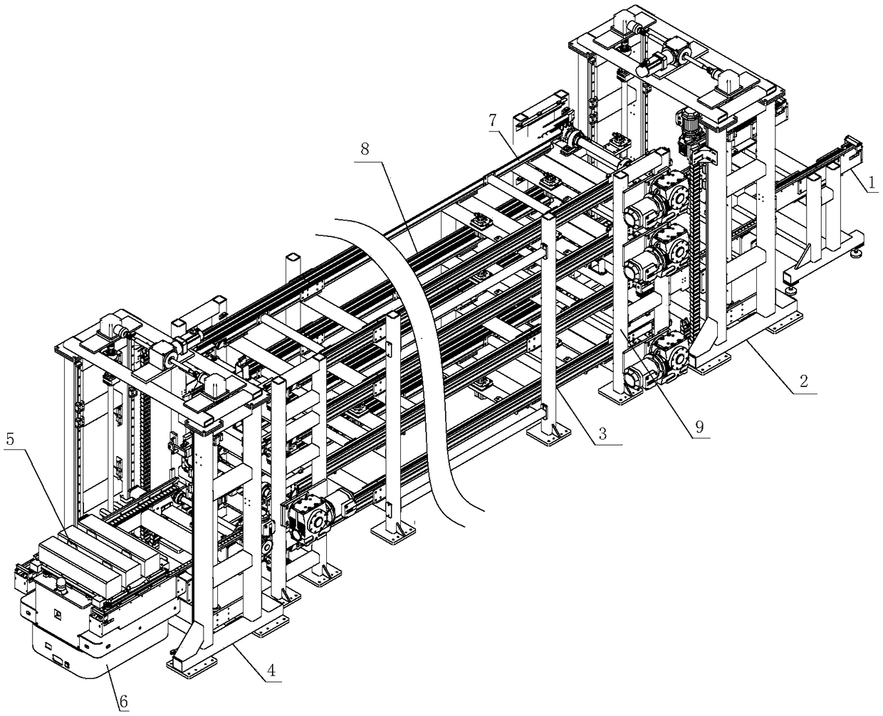
[0040] Such as figure 1 , a single crystal silicon ingot turnover device, including a transition platform 1, a feed elevator 2, a buffer line 3, a discharge elevator 4, a tooling 5, and an AGV trolley 6; wherein, the tooling 5 is placed on the transition platform 1, and the The feed lifter 2 moves the tooling 5 on the transition platform 1 into the cache line 3, and the discharge lifter 4 moves the tooling 5 on the buffer line 3 into the AGV trolley 6, and the tooling 5 includes A frame, on which a buffer layer is bonded to prevent the frame from damaging the single crystal silicon rod.
[0041] The turnover process of monocrystalline silicon rod in the present embodiment is as follows:
[0042] a. Place the empty tooling 5 on the transition platform 1.
[0043] b. The operator manually places the monocrystalline silicon rod in the empty tooling 5 on the transition platform 1 .
[0044] c. The feed elevator 2 transfers the tooling 5 equipped with silicon rods on the transit...
Embodiment 2
[0050] This embodiment introduces the structure of the cache line 3 in conjunction with the embodiment 1.
[0051] Such as figure 1 , the cache line 3 includes at least one layer of full-load line 7 that transfers the tooling 5 from the direction of the feeding elevator 2 to the direction of the discharging elevator 4 and the unloaded line 7 that transfers the tooling 5 from the direction of the discharging elevator 4 to the direction of the feeding elevator 2 Line 8.
[0052] The buffer line 3 includes a buffer rack 9 , and the full load line 7 and the empty line 8 are rotary conveyors arranged on the buffer rack 9 .
[0053] That is to say, the cache line 3 includes at least one layer of full load line 7 and one layer of empty line 8, the full load line 7 is used to transfer the tooling 5 loaded with monocrystalline silicon rods, and the empty line 8 is mainly used to transfer empty tooling 5. Therefore, the full-load line 7 and the empty-load line 8 should have the functio...
Embodiment 3
[0057] This embodiment introduces the structures of the feed elevator 2 and the discharge elevator 4 in combination with Embodiment 1 or Embodiment 2.
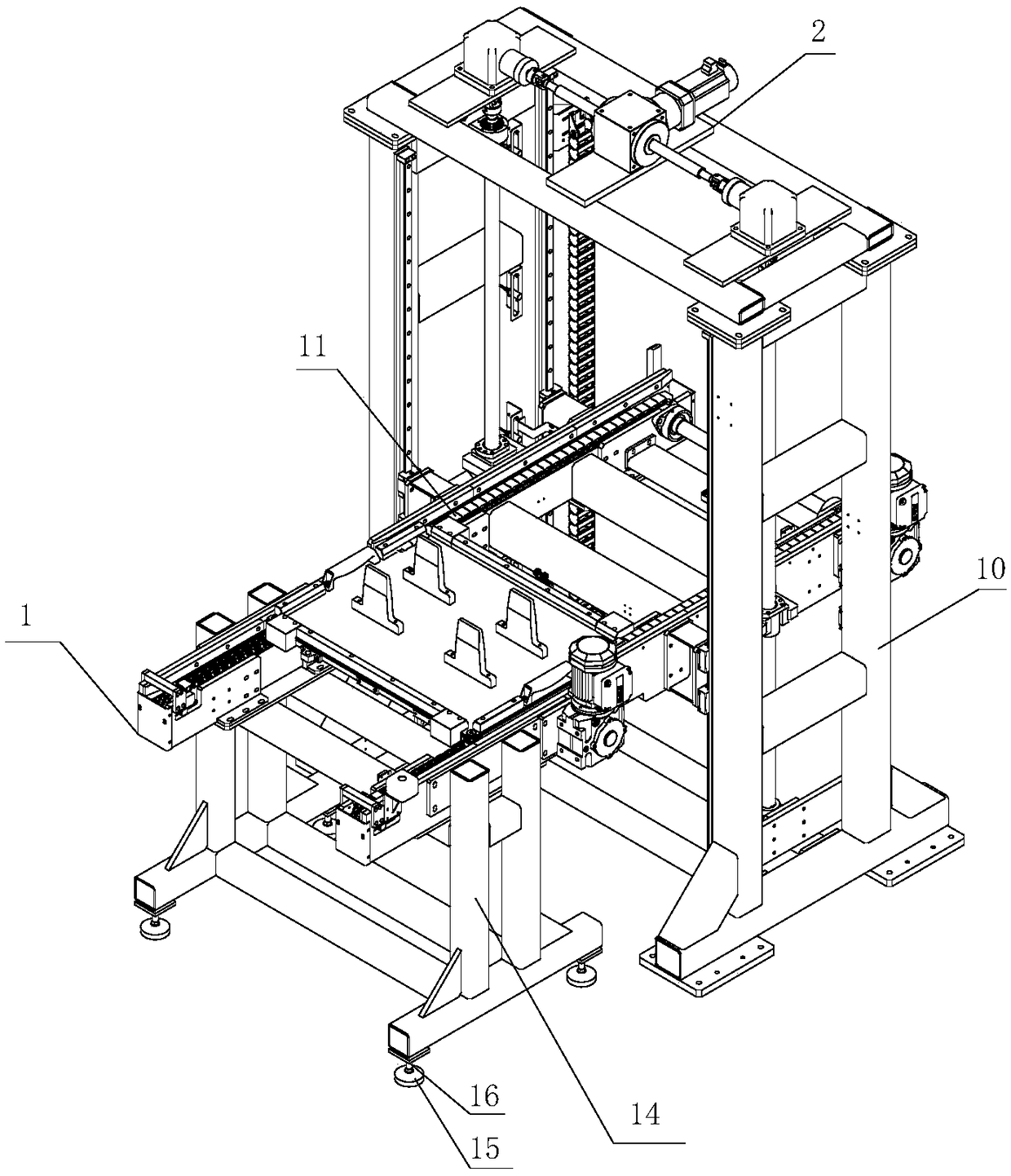
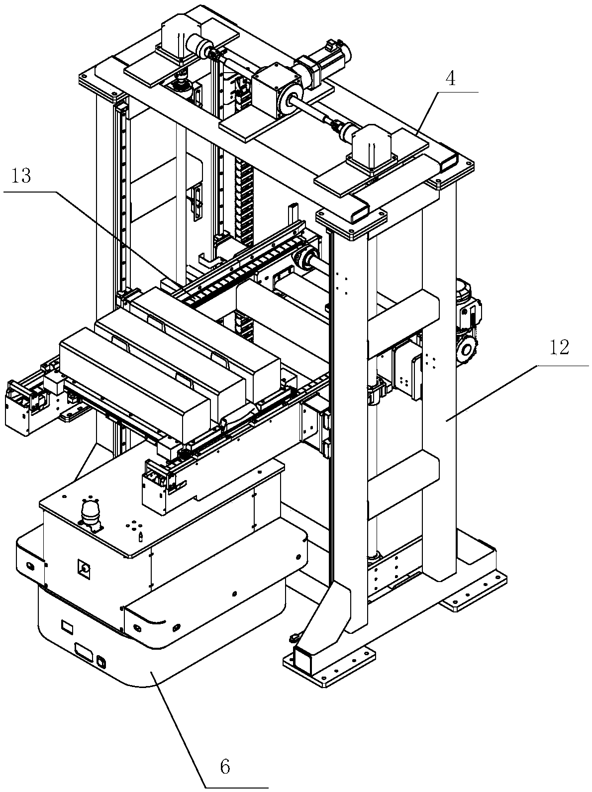
[0058] Such as figure 1 , figure 2 , image 3 , the feed elevator 2 includes a frame 10, the frame 10 can be formed by splicing rods, and a feed conveying mechanism 11 is arranged on the frame 10, and the feed conveying mechanism 11 is relatively to the frame 10 moves up and down, and the feed conveying mechanism 11 extends to the buffer line 3 to transfer the tooling 5 on the feed elevator 2 to the buffer line 3 .
[0059] Described feeding conveying mechanism 11 comprises the conveying frame that is slidably connected on the described frame 10, is provided with conveyer belt on described conveying frame, is provided with guide rail on described frame 10, is provided with on described conveying frame The chute cooperating with the guide rail is provided with a transmission chain on the frame 10 to drive the transmission f...
PUM
 Abstract
Description
Claims
Application Information
 - R&D Engineer
- R&D Manager
- IP Professional
- Industry Leading Data Capabilities
- Powerful AI technology
- Patent DNA Extraction
Browse by: Latest US Patents, China's latest patents, Technical Efficacy Thesaurus, Application Domain, Technology Topic.
© 2024 PatSnap. All rights reserved.Legal|Privacy policy|Modern Slavery Act Transparency Statement|Sitemap