
Reverse circulation pile driver

A technology of pile driver and reverse circulation, which is applied to sheet pile walls, drilling equipment, earthwork drilling, etc., can solve the problems of difference in wire rope length, increase in cost of pile drivers, and decrease in construction quality, so as to reduce construction errors and improve Work efficiency and service life, the effect of eliminating construction errors

Pending Publication Date: 2019-01-15
方圆电气股份有限公司
View PDF0 Cites 1 Cited by
  • Summary
  • Abstract
  • Description
  • Claims
  • Application Information

AI Technical Summary

Problems solved by technology

[0002] The working principle of the reverse circulation pile driver is to drive the drill bit up and down through the driving mechanism, and use the impact force to penetrate the drill bit into the ground for construction operations. This mechanical device is widely used in the fields of construction, water conservancy engineering, and forestry. Most of the existing pile drivers The steam or oil circuit is used as the source power to directly drive the drill bit to do work. Although this traditional power mode can drive the drill bit to move up and down for construction operations, it is only suitable for drill bits with a small mass. When the mass of the drill bit is large, the requirements for the piston cylinder Higher, resulting in an increase in the cost of the pile driver, but also has the problems of short service life and low work efficiency; in addition, the drill bit of the pile driver often controls the lifting of the drill bit through two separate wire ropes on both sides. In the process, due to the impact of the drill bit on the ground and rocks in the rock formation, after multiple constructions, the shaking of the steel wire rope will easily lead to the instability of the drill bit, and the length of the steel wire rope at both ends of the drill bit will be different, resulting in a certain degree of inclination of the drill bit. Keep the horizontal position all the time. If you use the inclined drill bit to continue construction, large construction errors will occur, resulting in a decline in construction quality

Method used


Image

  • Reverse circulation pile driver
  • Reverse circulation pile driver
  • Reverse circulation pile driver

Examples


Embodiment Construction

[0029] In order to clearly illustrate the technical features of this solution, the present invention will be described in detail below through specific implementation modes and in conjunction with the accompanying drawings.

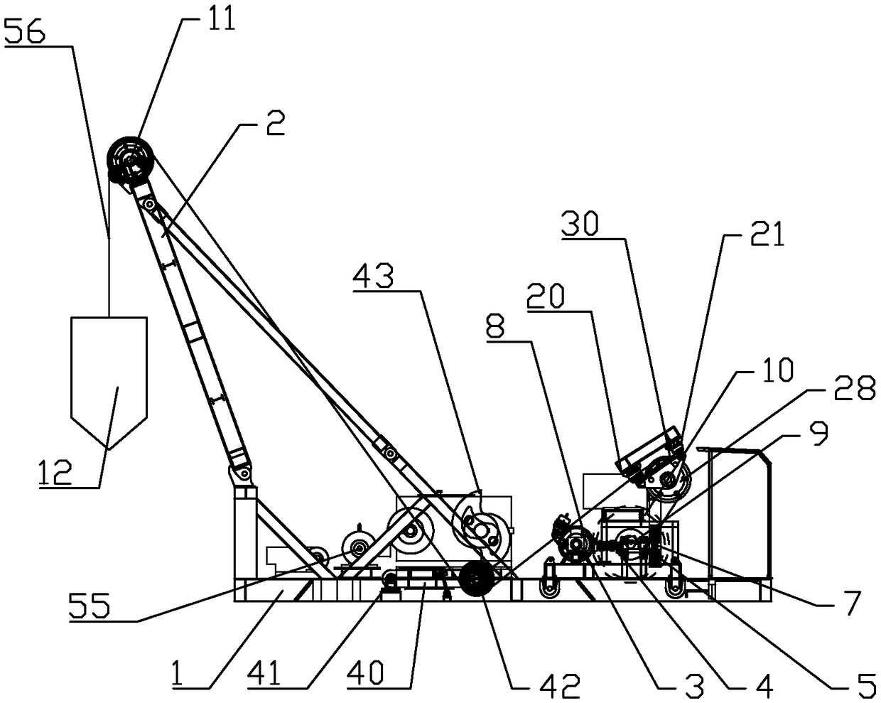
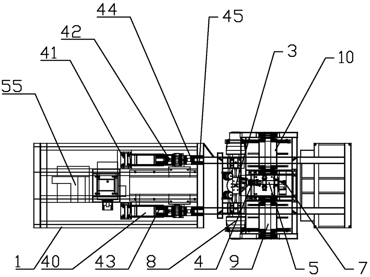
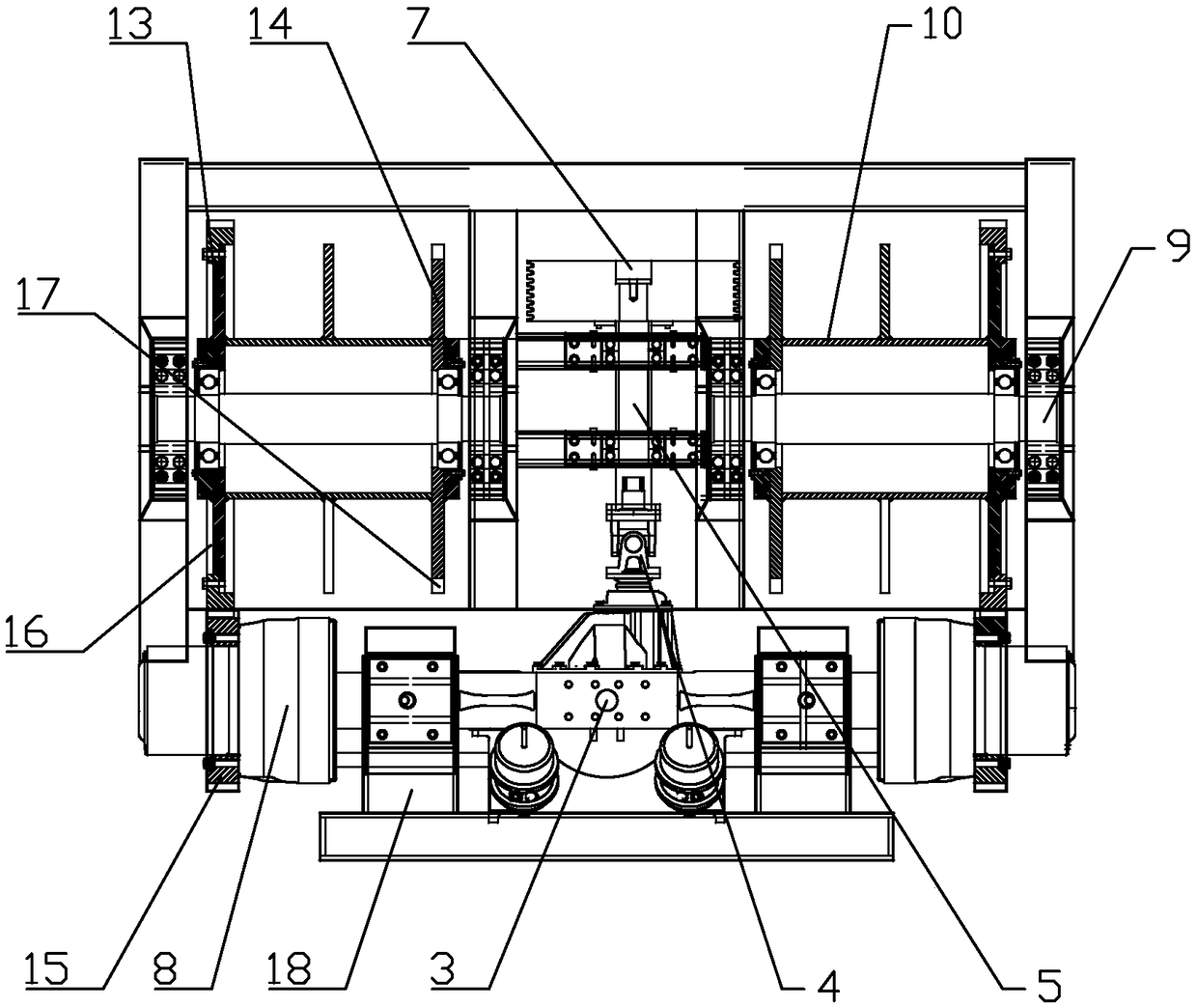
[0030] Such as Figure 1-12As shown in , a reverse circulation pile driver includes a base 1 and a frame assembly 2, a differential leveling mechanism is provided on the base 1, and a differential leveling mechanism is arranged on the frame assembly 2 above and behind the differential leveling mechanism. There are two swing-type wire rope sheave seats matched with the differential speed leveling mechanism, and two double-cam swing arm drive mechanisms matched with the two swing-type wire rope sheave seats are arranged at intervals on the base 1 on the front side of the differential speed leveling mechanism. The top of the frame assembly 2 is provided with a first wire rope pulley 11 matched with the two double-cam swing arm driving mechanisms, and the two...


PUM


Abstract

A reverse circulation pile driver comprises a base and a rack assembly. The base is provided with a differential leveling mechanism. Two swinging type steel wire rope wheel bases matched with the differential leveling mechanism are arranged on the rack assembly above the rear portion of the differential leveling mechanism in a spaced manner. The part, on the front side of the differential levelingmechanism, of the base is provided with two double-cam swing arm drive mechanisms in a spaced manner, wherein the two double-cam swing arm drive mechanisms are matched with the two swinging type steel wire rope wheel bases. The top of the rack assembly is provided with first steel wire rope wheels in an oppositely-spaced manner, wherein the first steel wire rope wheels are matched with the two double-cam swing arm drive mechanisms. Two sections of steel wire ropes wound around the differential leveling mechanism sequentially penetrate through the two swinging type steel wire rope wheel bases,the two double-cam swing arm drive mechanisms, the two first steel wire rope wheels and an impact drill bit arranged between the two first steel wire rope wheels; and the drill bit large in mass canbe driven to ascend and descend so as to finish the pile driving operation, the application range of the pile driver is enlarged, the work efficiency of the pile driver is improved, the service life of the pile driver is prolonged, and the cost of the pile driver is reduced.

Description

Technical field: [0001] The invention relates to a reverse circulation pile driver. Background technique: [0002] The working principle of the reverse circulation pile driver is to drive the drill bit up and down through the driving mechanism, and use the impact force to penetrate the drill bit into the ground for construction operations. This mechanical device is widely used in the fields of construction, water conservancy engineering, and forestry. Most of the existing pile drivers The steam or oil circuit is used as the source power to directly drive the drill bit to do work. Although this traditional power mode can drive the drill bit to move up and down for construction operations, it is only suitable for drill bits with a small mass. When the mass of the drill bit is large, the requirements for the piston cylinder Higher, resulting in an increase in the cost of the pile driver, but also has the problems of short service life and low work efficiency; in addition, the d...

Claims


Application Information

Patent Timeline
IPC IPC(8): E02D5/22E02D13/08E21B19/083
CPCE21B19/083E02D5/22E02D13/08
Inventor 李海旭王超谷朝彪张保辉
Owner 方圆电气股份有限公司
Learn More