High-voltage line polling device based on GPS

A high-voltage line and driving device technology, which is applied in the direction of measuring devices, cable installation, overhead line/cable equipment, etc., can solve problems such as damage and unusability, low efficiency, and brittle materials, so as to reduce air resistance and stabilize installation , the effect of easy installation

Active Publication Date: 2019-01-15
ELECTRIC POWER RES INST OF GUANGXI POWER GRID CO LTD +1
View PDF5 Cites 6 Cited by
  • Summary
  • Abstract
  • Description
  • Claims
  • Application Information

AI Technical Summary

Problems solved by technology

[0003] High-voltage overhead transmission lines generally use steel-cored aluminum stranded wires. Under the joint action of huge variable tension, bending stress caused by vibration, and long-term fatigue caused by rapid changes in temperature, the material of the transmission line will become brittle. It will inevitably cause surface damage to the high-voltage overhead transmission line, which will inevitably cause cracks and broken strands, which seriously threaten the wire itself...

Method used


Image

  • High-voltage line polling device based on GPS
  • High-voltage line polling device based on GPS
  • High-voltage line polling device based on GPS

Examples


Embodiment 1

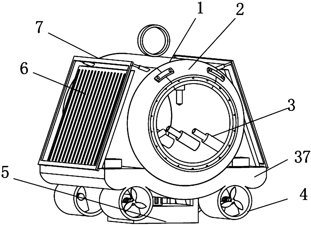
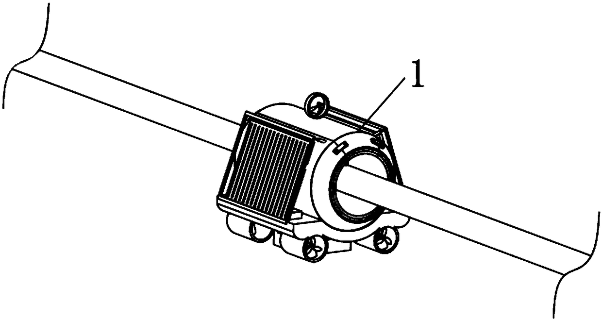
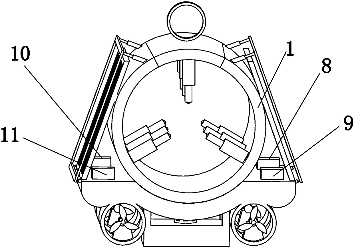
[0062] Embodiment one please refer to Figure 1-3 , a GPS-based high-voltage line inspection device, including a cylinder 1, a snow removal device 2, a clamping device 3, a drive device 4, a weight reduction device 5, a solar panel 6 and a protection device 7, characterized in that: Both ends of the cylinder body 1 are symmetrically fixed with snow removal devices 2, and the cylinder body 1 is provided with clamping devices 3, and there are nine clamping devices 3, and every three are evenly distributed on the cylinder body in a ring. 1, and three rows are equidistantly arranged, the bottom of the cylinder 1 is fixed with a base 37, and the four corners of the bottom of the base 37 are respectively fixed with a driving device 4, and the driving device 4 at one end of the base 37 is connected to the The driving device 4 located at the other end of the base 37 faces oppositely, and the weight reducing device 5 is fixed at the center of the bottom of the base 37, and the solar ce...

Embodiment 2

[0063] Embodiment 2 Please refer to Figure 4 , the snow removal device 2 includes an outer cover 28, an inner cover 29 and a hot blower 30, the outer cover 28 and the inner cover 29 are fixed on the end of the cylinder body 1, and the outer cover 28 is sleeved on the outside of the inner cover 29, the described A heat blower 30 is fixedly connected to the inner cover 29 .

Embodiment 3

[0064] Embodiment three please refer to Figure 5 , 6, the clamping device 3 includes a sliding cylinder 12, an electromagnet plate 13, a first spring 14, a baffle plate 15, a sliding rod 16 and a ball 17, the sliding cylinder 12 is fixed on the inner wall of the cylinder body 1, and the sliding cylinder 12 The inner bottom is fixed with an electromagnet plate 13, one side of the electromagnet plate 13 is fixedly connected to one end of the first spring 14, and the other end of the first spring 14 is fixedly connected to the baffle plate 15, and the baffle plate 15 is connected with the sliding cylinder 12 is slidingly fitted, the side of the baffle plate 15 away from the first spring 14 is fixedly connected to one end of the sliding rod 16, and the sliding rod 16 passes through the sliding tube 12, and the other end of the sliding rod 16 is movably embedded with a ball 17.


PUM


Abstract

The invention discloses a high-voltage line polling device based on a GPS (global positioning system). The polling device comprises a barrel, deicing devices, clamping devices, driving devices, a weight reduction device, a solar cell panel and a protection device; the deicing devices are symmetrically fixed at two ends of the barrel, the clamping devices are arranged in the barrel; the number of the clamping device is nine, and every three clamping devices are uniformly distributed at an inner all of the barrel in a ring, and three rows of clamping devices are equidistantly arranged; a base isfixed at the bottom of the barrel; one driving device is fixed at one of four corners at the bottom of the base, and the orientation of the driving device located at one end of the base is opposite to that of the driving device at the other end of the base. The high-voltage line periodic polling device based on the GPS disclosed by the invention is fast in polling speed and high in efficiency, the tiny fault in the high-voltage line can be detected so as to prepare in advance, and the device is low in power consumption, the solar energy is used for supplying power, the accurate positioning can be realized through the GPS after detecting the fault, thereby realizing fast overhauling.

Description

technical field [0001] The invention relates to the technical field of high-voltage line fault detection, in particular to a GPS-based high-voltage line inspection device. Background technique [0002] High-voltage lines usually refer to transmission lines that transmit voltages above 10kV (including 10kV). According to GB / T 2900.50-2008, definition 2.1, high voltage usually does not include 1000V. The voltage levels of high-voltage transmission lines in China are generally divided into: 35kV, 110kV, 220kV, 330kV, 500kV, 750kV, etc. [0003] High-voltage overhead transmission lines generally use steel-cored aluminum stranded wires. Under the combined action of huge variable tension, bending stress caused by vibration, and long-term fatigue caused by rapid changes in temperature, the material of the transmission line will become brittle. It will cause surface damage under the ground, which will inevitably lead to cracks and broken strands of high-voltage overhead transmissio...

Claims


Application Information

Patent Timeline
IPC IPC(8): G01R31/08G01R31/02G01S19/14H02G1/02H02G7/16
CPCG01R31/085G01S19/14G01R31/50H02G1/02H02G7/16Y04S10/52
Inventor 不公告发明人
Owner ELECTRIC POWER RES INST OF GUANGXI POWER GRID CO LTD
Why Eureka
Try Eureka