
A method and system for analyzing the influence of different hole-changing distances on signal quality

A signal quality and analysis method technology, applied in the field of signal transmission, can solve problems such as energy reflection and weakening signal quality, and achieve the effect of ensuring signal integrity, enhancing signal integrity and reliability, and ensuring safety

Inactive Publication Date: 2019-01-15
ZHENGZHOU YUNHAI INFORMATION TECH CO LTD
View PDF0 Cites 0 Cited by
  • Summary
  • Abstract
  • Description
  • Claims
  • Application Information

AI Technical Summary

Problems solved by technology

[0005] The purpose of the present invention is to provide a method and system for analyzing the influence of different hole changing distances on signal quality, aiming to solve the problem that the circuit board via holes in the prior art will cause energy reflection and weaken the signal quality, and obtain the effect of hole changing distance on signal quality. The impact of signal quality, to reduce signal loss and improve signal quality by setting the optimal via hole distance

Method used


Image

  • A method and system for analyzing the influence of different hole-changing distances on signal quality
  • A method and system for analyzing the influence of different hole-changing distances on signal quality
  • A method and system for analyzing the influence of different hole-changing distances on signal quality

Examples


Embodiment Construction

[0038] In order to clearly illustrate the technical features of the present solution, the present invention will be described in detail below through specific implementation methods and in conjunction with the accompanying drawings. The following disclosure provides many different embodiments or examples for implementing different structures of the present invention. To simplify the disclosure of the present invention, components and arrangements of specific examples are described below. Furthermore, the present invention may repeat reference numerals and / or letters in different instances. This repetition is for the purpose of simplicity and clarity and does not in itself indicate a relationship between the various embodiments and / or arrangements discussed. It should be noted that components illustrated in the figures are not necessarily drawn to scale. Descriptions of well-known components and processing techniques and processes are omitted herein to avoid unnecessarily lim...


PUM


Abstract

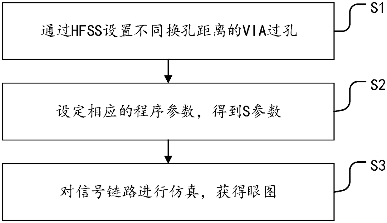
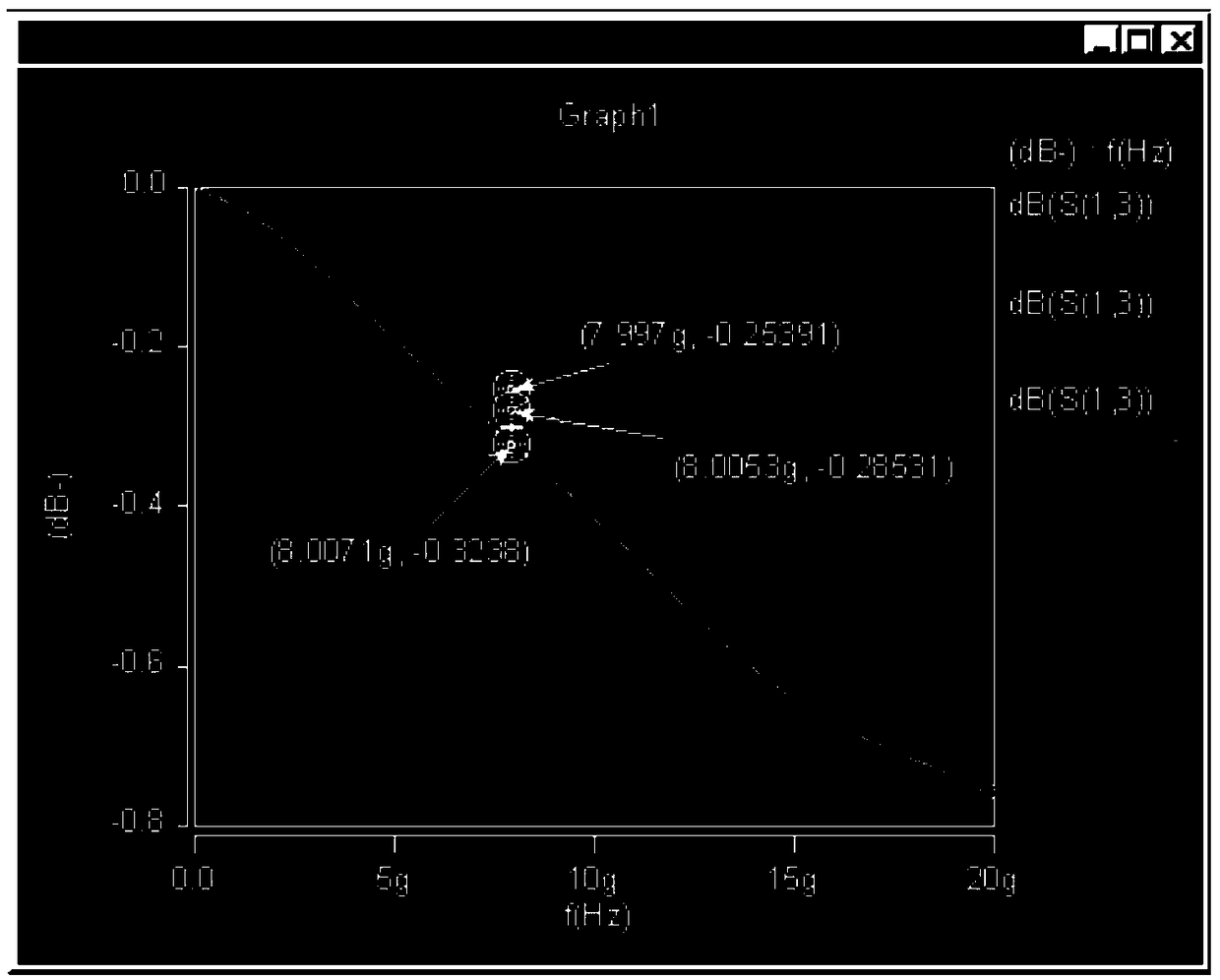
The invention provides a method and a system for analyzing the influence of different hole changing distances on signal quality, comprising the following steps: S1, VIA vias with different hole changing distances are arranged through HFSS; S2, setting corresponding program parameters to obtain S parameters; S3, simulating the signal link and obtaining the eye diagram. The invention provides a specific S value for different hole changing distances of a high-speed line through analysis, and expresses the influence of the via distance on the high-speed signal. And the signal link topology is simulated to compare the eye diagrams of different hole-changing distances by signal simulation, which makes the effect of hole-changing distances on the signal more intuitionistic and visible. The invention solves the problem that the circuit board via hole can cause energy reflection and weaken the signal quality in the prior art, obtains the influence of the hole changing distance on the signal quality, and realizes the reduction of the signal loss and the improvement of the signal quality by setting the optimum via hole distance.

Description

technical field [0001] The invention relates to the technical field of signal transmission, in particular to a method and system for analyzing the influence of different hole changing distances on signal quality. Background technique [0002] With the continuous improvement of digital circuit speed and clock frequency, in high-speed systems, signal integrity problems such as delay, reflection, attenuation, and crosstalk will occur when high-speed signals pass through interconnect lines. Signal integrity has become one of the key issues in the success of high-speed digital circuit design. [0003] The main factors affecting the signal integrity of high-speed digital PCB In addition to PCB design and PCB board material selection, via holes have a greater impact on signal integrity. In a high-speed multi-layer PCB, when the signal is transmitted from the top layer to an internal layer, connecting with a via hole will generate redundant via hole stubs, which greatly affect the ...

Claims


Application Information

Patent Timeline
Patent Type & Authority Applications(China)
IPC IPC(8): G06F17/50
CPCG06F30/20G06F30/30
Inventor 刘法志
Owner ZHENGZHOU YUNHAI INFORMATION TECH CO LTD
Learn More