A dual-rotation permanent magnet clamped linear stepping piezoelectric actuator and a driving method of the actuator

A piezoelectric driver, linear stepping technology, applied in piezoelectric effect/electrostrictive or magnetostrictive motors, generators/motors, electrical components, etc. , low resolution and other problems, to achieve the effect of long service life, novel method and high resolution

Pending Publication Date: 2019-01-15
ZHEJIANG NORMAL UNIVERSITY
View PDF7 Cites 0 Cited by
  • Summary
  • Abstract
  • Description
  • Claims
  • Application Information

AI Technical Summary

Problems solved by technology

[0010] The present invention aims to solve the problems of complex electronic control and mechanical structure, low resolution and short service life of the existing driver, and provides a double-rotating permanent magnet clamp linear stepping piezoelectric driver and a driving method for the driver

Method used


Image

  • A dual-rotation permanent magnet clamped linear stepping piezoelectric actuator and a driving method of the actuator
  • A dual-rotation permanent magnet clamped linear stepping piezoelectric actuator and a driving method of the actuator
  • A dual-rotation permanent magnet clamped linear stepping piezoelectric actuator and a driving method of the actuator

Examples


specific Embodiment approach 1

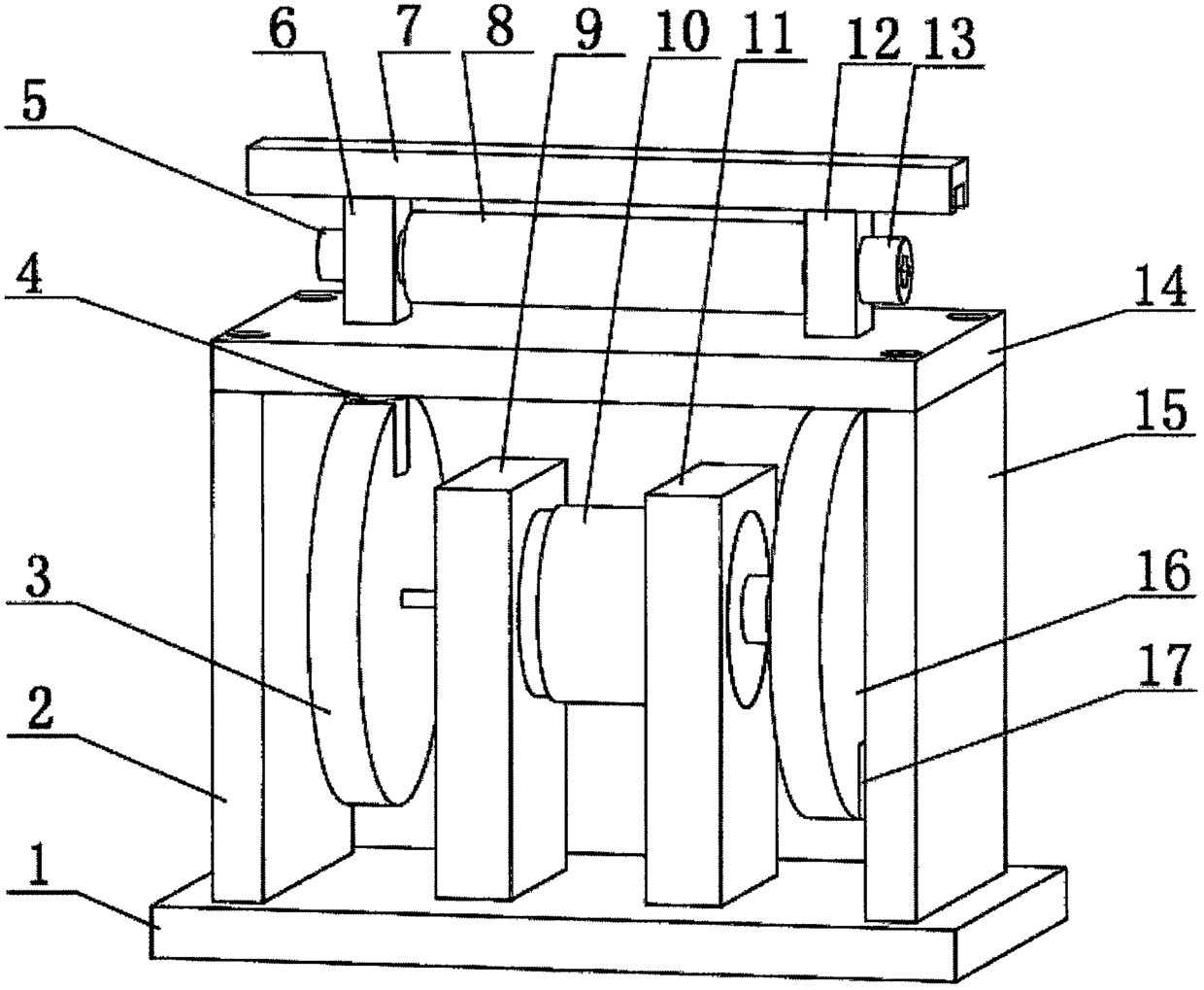
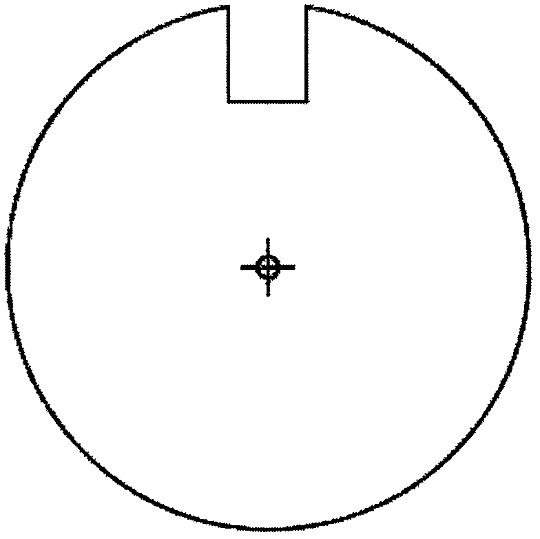
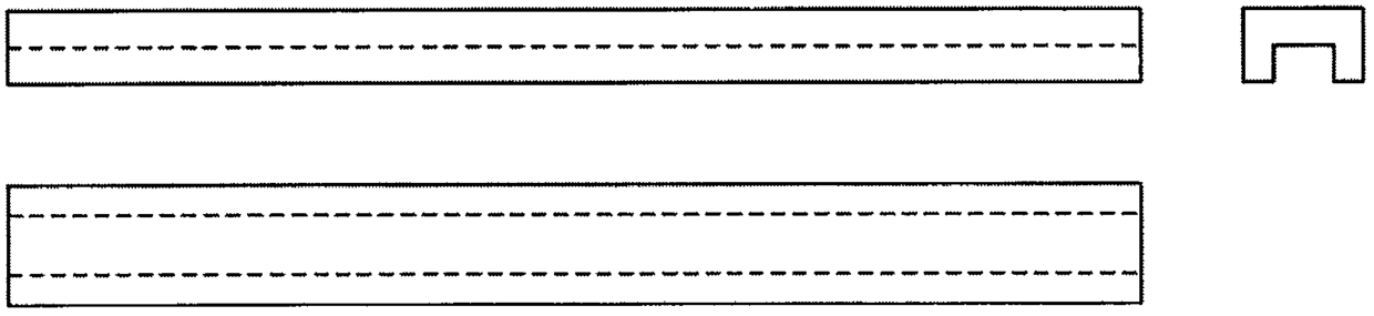
[0033] Specific implementation mode one: refer to Figure 1 to Figure 4 Specifically explaining this embodiment, a double-rotating permanent magnet clamp linear stepping piezoelectric driver described in the embodiment includes: a base 1, a DC motor bracket A9, a DC motor bracket B11, a double-protruded DC motor 10, a rotating Magnet fixed plate A3, rotating magnet fixed plate B16, magnet A4, magnet B17, support plate A2, support plate B15, working surface plate 14, piezoelectric stack 8, sliding magnetic block 6, fixed magnetic block 12, preload Screw 5, pre-tightening screw 13, moving steel bar 7;

[0034] The moving part is a moving steel bar 7, which is placed on the sliding magnetic permeable block 6 and the fixed magnetic permeable block 12;

[0035] The driving part is composed of a working surface plate 14, a piezoelectric stack 8, a sliding magnetic block 6, a fixed magnetic block 12, a pre-tightening screw 5, and a pre-tightening screw 13. The bottom of the fixed ma...

specific Embodiment approach 2

[0042] Specific implementation mode two: refer to Figure 5 , Figure 6 , Figure 7 Describe this embodiment in detail, the driving method of a kind of double-rotating permanent magnet clamp linear stepping piezoelectric driver described in the specific embodiment, the method is:

[0043] When the magnet B17 in the disk B in the time-sharing clamping magnetic field rotates to below the fixed magnetic permeable block 12 as Figure 7 As shown in (1), the piezoelectric stack 8 is not energized at this time, and the excitation signal of the piezoelectric stack 8 is Figure 6 In the section a-b in the middle, when the magnet A4 in the disk A rotates to the bottom of the sliding magnetic block 6, the piezoelectric stack 8 is continuously energized as Figure 6 Middle section c-d, at this time, the piezoelectric stack 8 will elongate simultaneously with the sliding magnetic block 6 on the left side, and due to the magnetic force, it will drive the upper moving steel bar 7 to slide...


PUM


Abstract

The invention relates to a double-rotating permanent magnet clamped linear stepping piezoelectric driver and a driving method of the driver, belonging to the technical field of precision instruments and equipment. At both end of that piezoelectric stack, A magnetic conductive block is fix and screwed, piezoelectric stack and sliding magnetic block, A magnetic permeable block is fix to form a driving part, A moving steel bar is placed on the drive portion, A magnetic permeable block is fixedly connected with that working surface plate, A support plate is fixedly connecte with an upper surface of a bottom plate, a magnet is fixedly connected with a magnet fix plate, that magnet fixed plate is fixed on an output shaft of both ends of a DC motor, and the position of the magnet is symmetrical with respect to a central axis of the DC motor, the DC motor is fixedly connected with a bracket, and the bracket is fixedly connected with the bottom plate. The invention has the advantages of solvingthe problems that the friction and wear of the existing precision driving device are serious and the precision is difficult to be improved from the angle of improving the generation mode of the clamping friction force, and improving the output stability of the piezoelectric step-by-step actuator.

Description

technical field [0001] The invention belongs to the technical field of precision instruments and equipment, in particular to a linear stepping piezoelectric driver. Background technique [0002] In order to meet the precise positioning requirements of aerospace / biomedical / MEMS / precision manufacturing and other fields, precision drives based on the principles of electromagnetic / electrostatic / thermal deformation / magnetostriction / shape memory alloy / electrodeformation / piezoelectricity (or The research on motor / motor / actuator / actuator, etc.) has become a hot spot both at home and abroad. Each type of driver has its own advantages and applicable fields. The piezoelectric driver has the characteristics of high resolution, precise positioning, simple structure, convenient control, and no electromagnetic interference. Therefore, it has a wider range of applications and has been used in biological cell operations, micro-electromechanical In systems such as micro-nano indentation and ...

Claims


Application Information

Patent Timeline
Patent Type & Authority Applications(China)
IPC IPC(8): H02N2/02H02N2/06
CPCH02N2/021H02N2/06
Inventor 程光明王仁明温建明
Owner ZHEJIANG NORMAL UNIVERSITY
Why Eureka
Try Eureka