Lateral-filtering-type fish tank

A filter type, fish tank technology, applied in fish farming, climate change adaptation, water/sewage treatment, etc., can solve problems such as uncontrollable food intake

Active Publication Date: 2019-01-18
芜湖乐佳自动化机械有限公司
View PDF7 Cites 4 Cited by
  • Summary
  • Abstract
  • Description
  • Claims
  • Application Information

AI Technical Summary

Problems solved by technology

[0003] In the feeding process of the above patent, only one kind of fish food can be provided, and the amount of food output at one time cannot be controlled

Method used


Image

  • Lateral-filtering-type fish tank
  • Lateral-filtering-type fish tank
  • Lateral-filtering-type fish tank

Examples


Embodiment 1

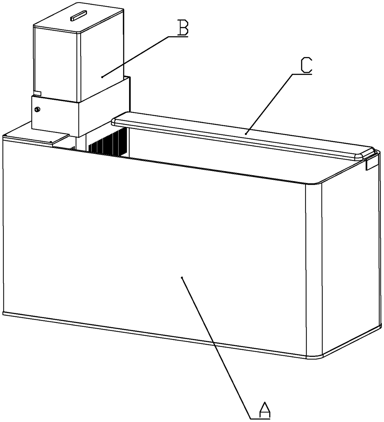
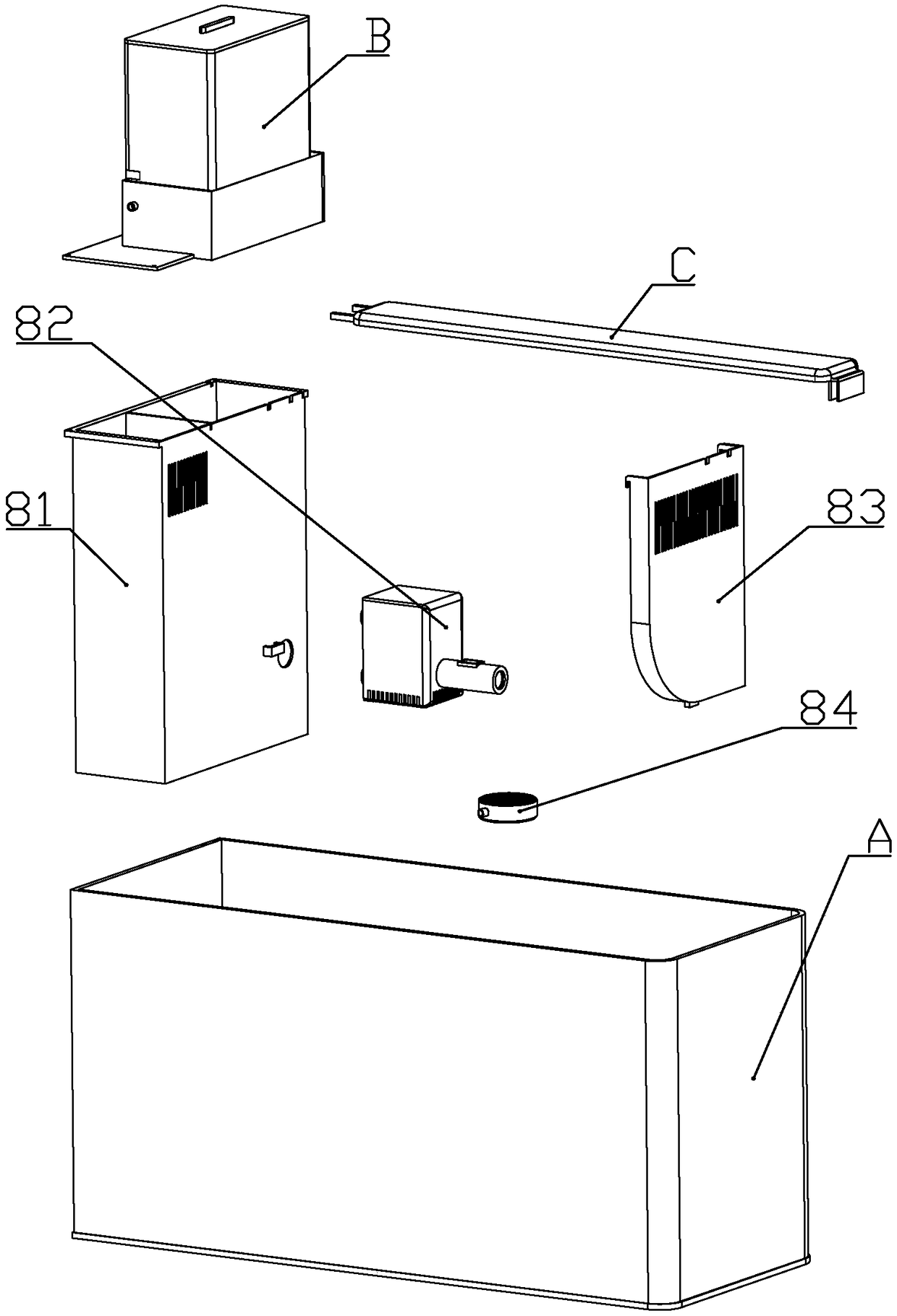
[0067] according to Figure 1 to Figure 17 As shown, a side filter fish tank described in this embodiment includes a cylinder body A; one side of the cylinder body is detachably connected with a filter assembly for filtering the water in the cylinder body; the upper end of the filter assembly is detachable Feed assembly B is connected.

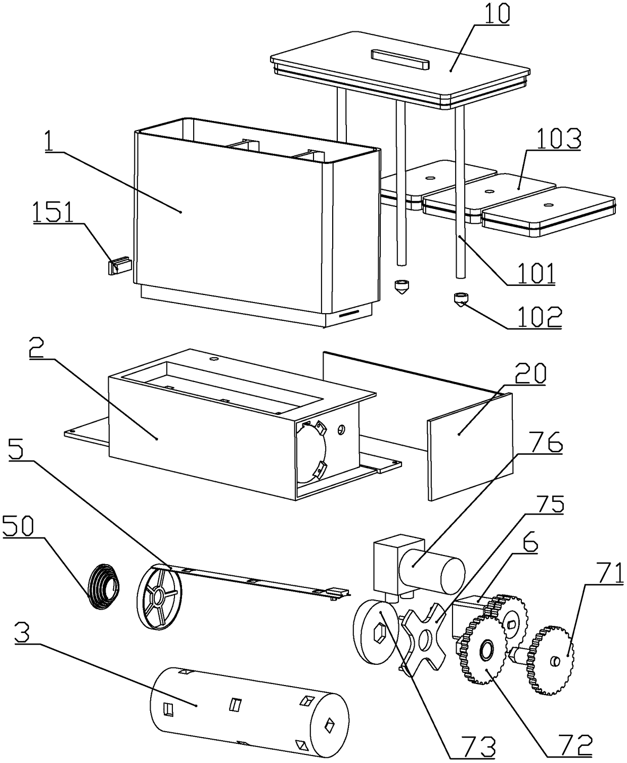
[0068] The feeding assembly includes a base 2 installed on one side of the upper end of the cylinder body, and a material box 1 installed on the upper end of the base, and a material box cover 10 is detachably connected to the material box; There are multiple storage cavities 11 for storing fish food; different kinds of granular feed can be stored in each storage cavity, so as to provide different kinds of nutrition for fish.

[0069] The front part of the base is a rotating column installation groove 22 with the axis along the horizontal direction; the side of the rotating column installation groove on the base is a gear installation groove ...

Embodiment 2

[0148] according to Figure 18 to Figure 19 As shown, the difference between this embodiment and Embodiment 1 is that: the upper part of the foam shell is formed with a foam water outlet 835 located above the liquid level in the cylinder.

[0149] A second valve tube 826 that can cover the intubation pipe of the foam material shell is slidably connected in the water spray joint; the end surface of the second valve tube close to the water pump is formed with a valve driven by water flow to drive the second valve tube to move. The second blocking wall 8261; the end surface of the second valve tube away from the water pump is fixedly connected with a second valve tube magnet 8262 repelling each other with the joint magnet.

[0150] The diameter of the inner wall of the second valve pipe is smaller than the diameter of the inner wall of the outlet pipe of the water pump.

[0151] The controller controls the feeding component to work, so that the feed falls into the foaming tank. ...

Embodiment 3

[0157] This embodiment makes the following improvements on the basis of the foregoing embodiments: the upper ends of the valve plates are fixedly connected with sealing gaskets on one side of each material port; The material openings are sealed against each other, so that the material storage chamber is in a closed environment.

[0158] When the controller controls the air pump to pump air in the storage chamber, the storage chamber can be evacuated, so that fish food can be stored better.

[0159] With the operation of the air pump, the air pressure in the material storage chamber decreases, so that the sealing piston moves downward, and always touches the upper end of the fish food. When performing the next air pumping work, it is only necessary to pump out the air below the sealing piston in the material storage chamber. That is, the extraction amount of air is reduced, and the workload of the air pump is reduced.


PUM

PropertyMeasurementUnit
thicknessaaaaaaaaaa

Abstract

The invention discloses a lateral-filtering-type fish tank. The tank comprises a tank body, a filtering assembly and a feeding assembly. The feeding assembly comprises a base and a feed box, and a plurality of feed storing cavities used for storing fish feed are formed in the feed box and can store multiple types of fish feed. Feed falling pipes are formed at the lower ends of all the feed storingcavities. A rotary column is rotatably installed in the base. A plurality of feed storing grooves with different depths are formed in the outer wall of the rotary column to control the fish feed amount in the process of feeding fish; a valve piece is slidably connected with the inside of the base in the axial direction of the rotary column; a feed through opening is formed in the valve piece. A discharging passage capable of making all the feed storing grooves separately communicated with the tank body is formed in the lower end of the base. A motor capable of driving the rotary column to rotate or driving the valve piece to move is installed in the base. The control over selection of feed and feeding amount is achieved through a single stepping motor.

Description

technical field [0001] The invention belongs to the technical field of fish tanks, and in particular relates to a side filter fish tank. Background technique [0002] The Chinese patent document whose document number is CN207589883U discloses a fish tank for intelligent automatic feeding. A discharge cylinder is provided; a main shaft is arranged in the discharge cylinder; a discharge impeller is arranged on the main shaft and is located in each discharge cylinder; gears and racks are arranged at both ends of the main shaft; There is a screw sleeve in the middle of the lower end of the feeding hopper, and a screw is installed in the screw sleeve; a motor is installed at one end of the screw; the motor is connected to the controller; a humidity sensor and a heating tube are installed in the feeding hopper; Waist baffle in the shape of a waist triangle; the width of the bottom surface of the baffle is greater than the width of the discharge barrel. It can realize uniform aut...

Claims


Application Information

Patent Timeline
Patent Type & Authority Applications(China)
IPC IPC(8): A01K63/00A01K61/80A01K63/04A01K63/06C02F1/00C02F103/20
CPCA01K63/003A01K63/042A01K63/045A01K61/85Y02A40/81
Inventor 麻景峰
Owner 芜湖乐佳自动化机械有限公司
Why Eureka
Try Eureka