A kind of energy-saving automatic water treatment equipment with backwash grille

A water treatment equipment and backwashing technology, which is applied in the field of water treatment, can solve the problems of reducing the working efficiency of the equipment, being easily taken away by the water flow, and low throughput, so as to increase the amount of passing water, reduce the probability of blocking, and improve the effect Effect

Active Publication Date: 2020-10-30
德州派尔机械设备有限公司
View PDF5 Cites 0 Cited by
  • Summary
  • Abstract
  • Description
  • Claims
  • Application Information

AI Technical Summary

Problems solved by technology

[0003] Sewage treatment equipment often needs to be pretreated through the grid pool. In small treatment equipment, fixed grids are generally used, and the grids need to be replaced frequently. When replacing, the operation of the equipment needs to be stopped, and the dirt will block when the fixed grid is used. The longer the use of the through hole, the lower the water flow, both of which will reduce the working efficiency of the equipment; while the rotary grille cleans the grille by scraping the material, but the grille has a through hole, and the dirt It is often hidden in the hole without being scraped off. When it is rotated to the filtered side, the dirt in the hole is easily taken away by the water flow, and the grille cannot be cleaned thoroughly without allowing the dirt in the hole to enter the next procedure. Moreover, the rotary grille needs to work continuously, which consumes a lot of power

Method used


Image

  • A kind of energy-saving automatic water treatment equipment with backwash grille
  • A kind of energy-saving automatic water treatment equipment with backwash grille
  • A kind of energy-saving automatic water treatment equipment with backwash grille

Examples


Embodiment Construction

[0025] The following will clearly and completely describe the technical solutions in the embodiments of the present invention with reference to the accompanying drawings in the embodiments of the present invention. Obviously, the described embodiments are only some, not all, embodiments of the present invention. Based on the embodiments of the present invention, all other embodiments obtained by persons of ordinary skill in the art without making creative efforts belong to the protection scope of the present invention.

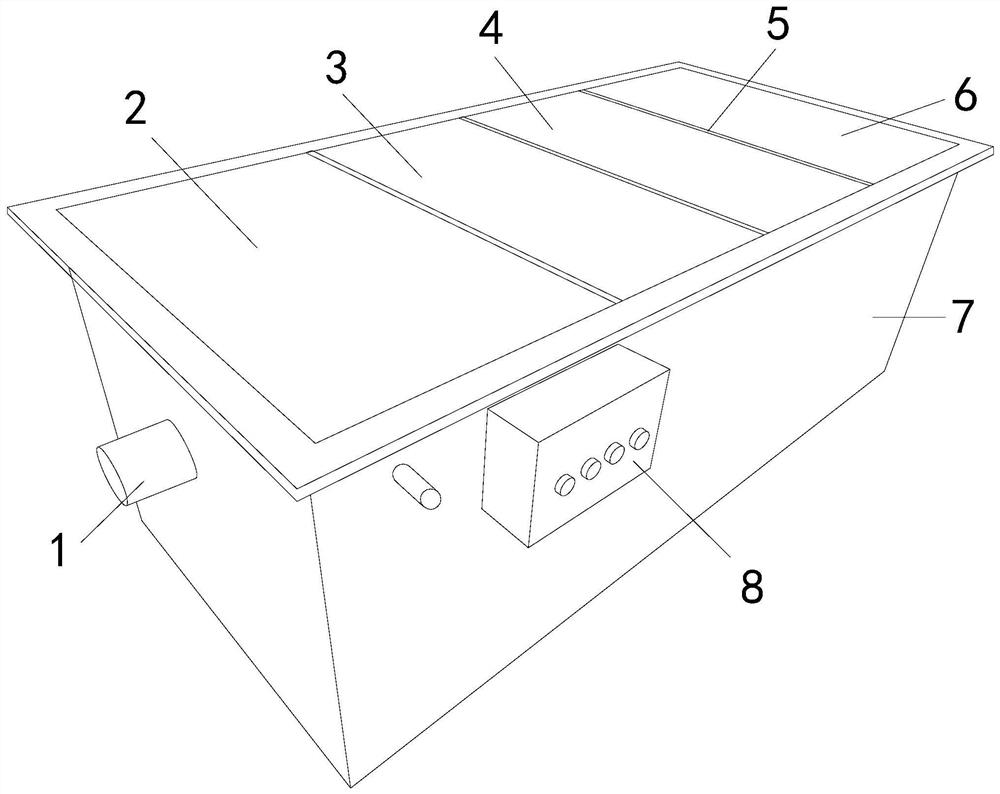
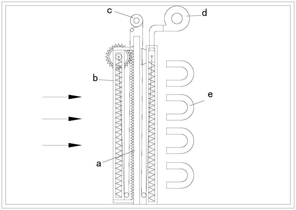
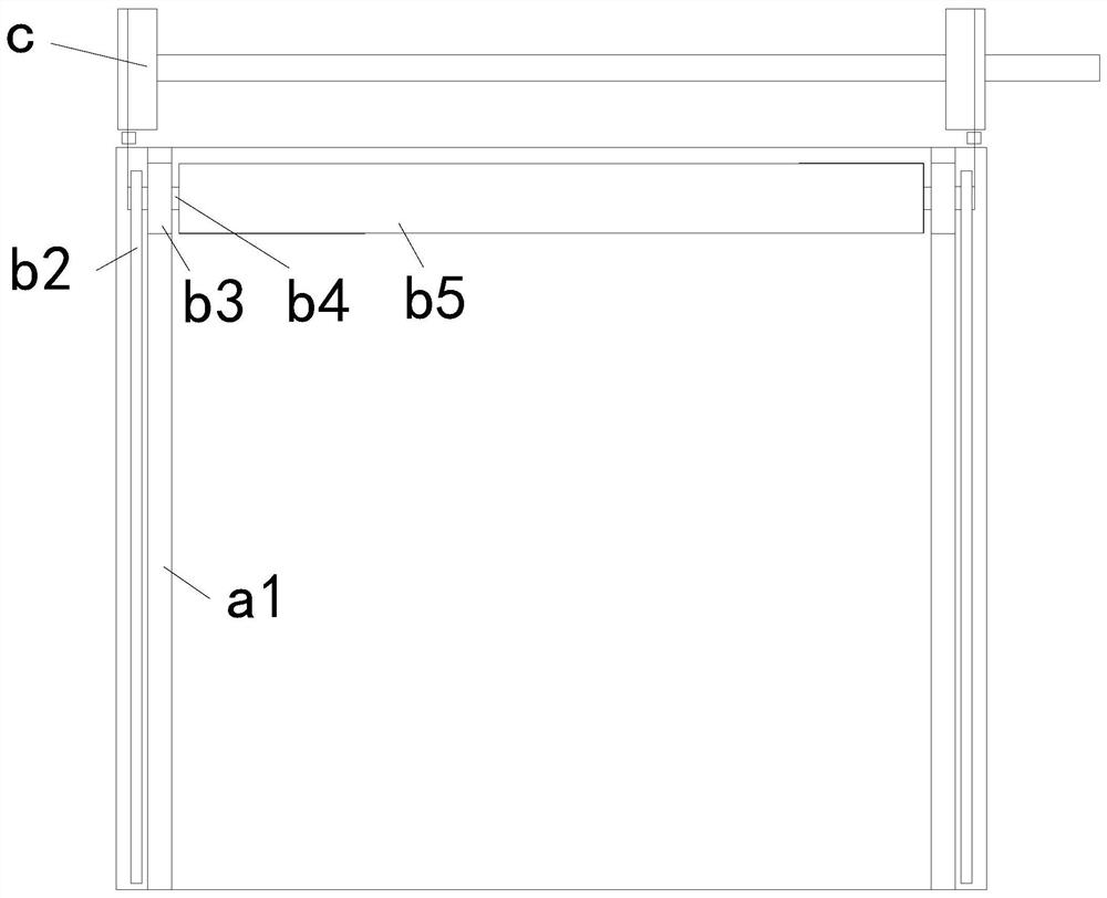
[0026] see Figure 1-6 , the present invention provides a technical scheme of energy-saving automatic water treatment equipment with a backwash grille: its structure includes a water inlet 1, a grille pool 2, an aerobic pool 3, an MBR pool 4, a sludge storage pool 5, and a partition plate 6 , a box body 7, a controller 8, a controller 8 is installed on the outside of the box body 7, and the inside of the box body 7 is separated into a grid pool 2, an aerobic p...


PUM


Abstract

The invention discloses energy-saving automatic water treatment equipment with a backwashing barrier. The energy-saving automatic water treatment equipment structurally comprises a water inlet, a barrier pool, a facultative tank, a pool, a sludge storage pool, partitioning plates, a box body and a controller, wherein the controller is arranged at the outer side of the box body; the inner part of the box body is partitioned into the barrier pool, the facultative tank, the pool and the sludge storage pool in sequence by the partitioning plates; the barrier pool is communicated with the water inlet; the vertical barrier plate is arranged at the middle part of the inside of the barrier pool; a brushing device is arranged at the left side of the barrier plate. The energy-saving automatic watertreatment equipment disclosed by the invention has the beneficial effects that the barrier plate is cleaned by matching of brushing and airflow recoil, so that the brushed dirt can be prevented from rushing towards one side for filtering; working does not need to be stopped in cleaning, so that the working efficiency is improved; a U-shaped pipeline can carry out reverse washing on the barrier plate by utilizing the own inertia of water flow, so that the probability of blockage of through holes of the barrier plate can be reduced, and the water passing volume can be increased; by the U-shapedpipeline, the cleaning times can be reduced, continuous working is not needed and the power consumption cost can be reduced.

Description

technical field [0001] The invention relates to the field of water treatment, in particular to an energy-saving automatic water treatment device with a backwash grille. Background technique [0002] Water treatment includes sewage treatment and water purification treatment. Sewage treatment is widely used and can purify sewage. [0003] Sewage treatment equipment often needs to be pretreated through the grid pool. In small treatment equipment, fixed grids are generally used, and the grids need to be replaced frequently. When replacing, the operation of the equipment needs to be stopped, and the dirt will block when the fixed grid is used. The longer the use of the through hole, the lower the water flow, both of which will reduce the working efficiency of the equipment; while the rotary grille cleans the grille by scraping the material, but the grille has a through hole, and the dirt It is often hidden in the hole without being scraped off. When it is rotated to the filtered...

Claims


Application Information

Patent Timeline
Patent Type & Authority Patents(China)
IPC IPC(8): B01D29/64B01D29/68
CPCB01D29/6415B01D29/6423B01D29/688
Inventor 杨伟增
Owner 德州派尔机械设备有限公司
Why Eureka
Try Eureka