
Inlet flue triangular truss suspension type denitration reactor device

A denitrification reactor and inlet flue technology, applied in chemical instruments and methods, dispersed particle separation, separation methods, etc., can solve the problems of not contributing to the force of the overall structure, not participating in the overall calculation, and increasing the load of the frame column. Achieve the effects of avoiding the limitations of stability and slenderness ratio, reducing the calculation length, and reducing the earthquake effect

Pending Publication Date: 2019-01-18
DATANG ENVIRONMENT IND GRP
View PDF3 Cites 1 Cited by
  • Summary
  • Abstract
  • Description
  • Claims
  • Application Information

AI Technical Summary

Problems solved by technology

[0005] (1) The main components of the traditional denitrification reactor structure are mostly pressure-bearing components, and the overall stability and local stability of the components need to be considered, the slenderness ratio control is stricter, and the cross-section is larger
[0006] (2) The inlet flue is only considered as an independent component, and does not participate in the overall calculation, and does not contribute to the force of the overall structure
[0007] (3) The inlet flue will receive a large thrust under the action of the internal pressure of the flue gas, and the thrust point is far away from the support, and the moment arm is large, forming a large bending moment, which further increases the load on the frame column
[0008] (4) Since the outlet flue is set directly below the denitrification reactor, the fulcrum cannot be added under the internal support beam of the denitrification reactor, only two ends are supported

Method used


Image

  • Inlet flue triangular truss suspension type denitration reactor device
  • Inlet flue triangular truss suspension type denitration reactor device
  • Inlet flue triangular truss suspension type denitration reactor device

Examples


specific Embodiment

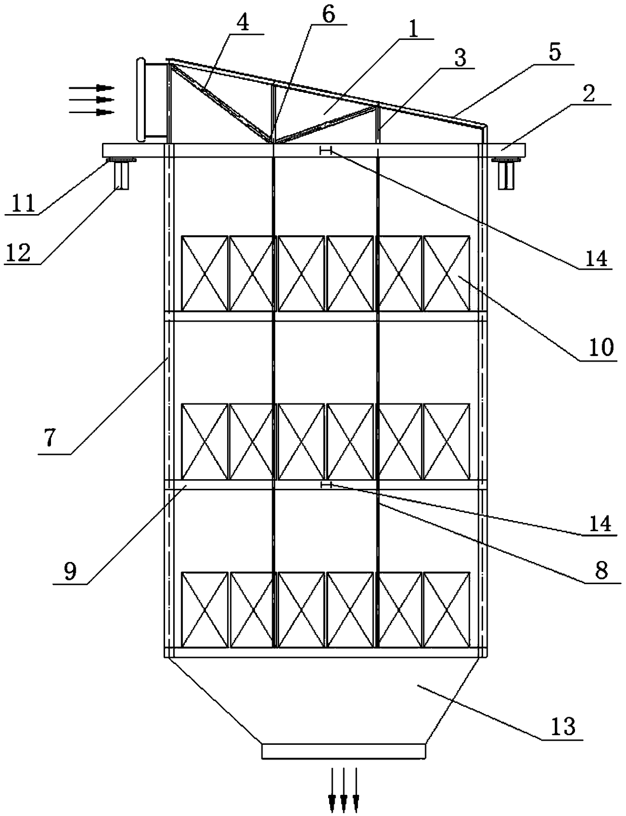
[0048] The SCR denitrification reactor device of an ironworks in Shanghai, the seismic fortification intensity of this project is 7 degrees, the design basic seismic acceleration value is 0.13g, the design earthquake grouping is the first group, the site category is second class, and the basic wind pressure is 0.40KN / m 2 ; The size of the denitrification reactor is 10.20m*6.60m*12.00m (height), and the height of the inlet flue is 1.65m. The overall model is calculated and subjected to force analysis in the structural design software, and finally the cross-sections of the triangular truss chord and the components of the denitrification reactor body are determined as follows: figure 1 shown.

[0049] During installation, the two ends of the support beam 2 (support rectification grid and inlet flue) on the top of the traditional denitrification reactor are extended to the peripheral steel support platform of the denitrification reactor as the lower chord of the triangular truss 6...


PUM


Abstract

The invention discloses an inlet flue triangular truss suspension type denitration reactor device. According to the device disclosed by the invention, two ends of a top supporting beam of a traditional denitration reactor body extend to a peripheral steel bracket platform of a denitration reactor to be used as a low chord rod of a triangular truss; one triangular truss is arranged above each supporting beam; a hoisting rod is mounted at a node of the low chord rod and is connected with each layer of a catalyst module supporting beam at the lower side; a reactor wall plate is mounted on a peripheral hoisting rod to form the denitration reactor body; an outlet flue is mounted at the lower end of the denitration reactor body; and limiting devices in the horizontal direction are arranged at four sides of the middle part of the reactor respectively to form the suspension type denitration reactor device. The inlet flue triangular truss suspension type denitration reactor device has the beneficial effects that the device can be used for sufficiently releasing structure performance of an original inlet flue, stress characteristics of a whole structure are changed and limitation on the stability and slenderness ratio of a compressed member is avoided; the section of the member is wholly reduced, the self weight is reduced and the cost is saved; and a suspension type structure is utilized so that the earthquake effect on the member also can be reduced.

Description

technical field [0001] The invention relates to the technical field of denitrification, in particular to a denitrification reactor device suspended by a triangular truss of an inlet flue. Background technique [0002] The denitrification reactor device is the core link of the selective catalytic reduction (SCR) flue gas denitrification complete set technology, which is mainly composed of the denitrification reactor body, the inlet flue, and the outlet flue. The traditional structure is that the body of the denitration reactor is supported by four corner columns, the top is connected to the inlet flue, and the bottom is connected to the outlet flue. The main pressure-bearing component is the quadrangular frame column of the reactor. In addition to supporting the overall load of the entire denitrification reactor system, it also bears the horizontal load caused by the internal pressure of the flue. The frame column bears a large load and has a large cross-section. [0003] Th...

Claims


Application Information

Patent Timeline
Patent Type & Authority Applications(China)
IPC IPC(8): B01D53/86B01D53/56
CPCB01D53/8631
Inventor 李鹏张鹏远宋红兵张磊卫凯华詹蓓蓓征少卿旷钐陈慧雁郭家奇
Owner DATANG ENVIRONMENT IND GRP
Learn More