Cold-drawn rivet gun, cold-drawn rivet and cold-drawn riveting method

A technology for pulling rivets and rivet guns, which is applied in the field of cold-drawing rivets, cold-drawing riveting, and cold-drawing rivet guns. It can solve problems such as ring teeth or threads that are easily damaged, and achieve improved service life, uniform force, and good transmission effects. Effect

Active Publication Date: 2020-08-04
成都浩益科技有限公司
View PDF8 Cites 0 Cited by
  • Summary
  • Abstract
  • Description
  • Claims
  • Application Information

AI Technical Summary

Problems solved by technology

[0003] The purpose of the present invention is to provide a cold-drawn rivet gun, a cold-drawn rivet and a cold-drawn riveting method to solve the problem that the ring teeth or threads on the nail grabber are easily damaged when the existing cold-drawn rivet gun is riveting the cold-drawn rivet. And improve the quality and service life of the cold-drawn rivet gun, thereby improving the riveting quality and reliability

Method used


Image

  • Cold-drawn rivet gun, cold-drawn rivet and cold-drawn riveting method
  • Cold-drawn rivet gun, cold-drawn rivet and cold-drawn riveting method
  • Cold-drawn rivet gun, cold-drawn rivet and cold-drawn riveting method

Examples


Embodiment 1

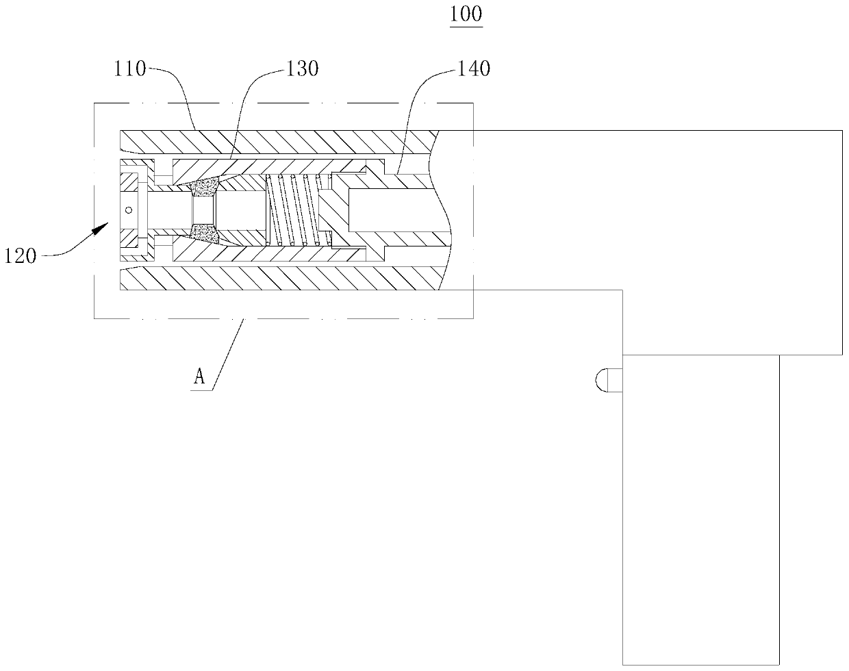
[0050] Please refer to figure 1 , a cold-drawn rivet gun 100, including a gun casing 110, a power unit, a gun handle, a start button, a reversing valve and other components; the middle cavity of the gun casing 110 is sequentially provided with a limit device 120, The clamping shell 130, the connecting seat 140 and the power device, and the limiting device 120, the clamping shell 130, the connecting seat 140 and the power device are connected in sequence. The limiting device 120 is located at the muzzle of the gun, the power unit is connected to the gun shell 110 , and the movement direction of the connecting seat 140 is opposite to that of the gun shell 110 . In this embodiment, the power device is a hydraulic drive device, obviously, the power device may also be an electric drive device or a manual drive device.

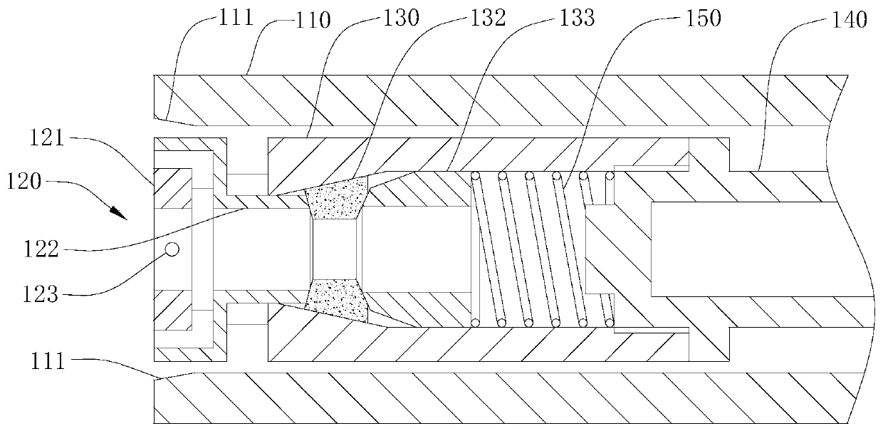
[0051] Please refer to figure 2 , The inner surface of the gun shell 110 close to the muzzle is provided with an extruding slope 111 . The extrusion slope 111 o...

Embodiment 2

[0069] Please refer to Figure 17 and Figure 18The difference between this embodiment and Embodiment 1 is that the cold-drawn rivet 200 is not provided with a breaking groove 216, and a connecting section 217 is provided between the riveting section 212 and the clamping section 213, and the axes of the connecting section 217 and the riveting section 212 coincide. And the diameter of the connecting section 217 is consistent with the diameter of the riveting section 212, and the diameter of the connecting section 217 is greater than the diameter of the clamping section 213, so that the cold-drawn rivet 200 is stepped. At this time, the cold-drawn rivet 200 is a short-tail cold-drawn rivet. The connection method between the cold-drawn rivet 200 and the cold-drawn rivet gun 100 of the present invention is applied to short-tailed rivets.

[0070] The method and principle of riveting the cold-drawn rivet 200 with the cold-drawn rivet gun 100 of this embodiment are the same as thos...


PUM


Abstract

The invention discloses a cold-draw riveting gun, a cold-pull rivet and a cold-pull riveting method, and belongs to the technical field of riveting. The tail part of the cold-draw rivet is provided with a clamping ring groove, the riveting gun comprises a gun shell, a clamping shell and connecting seat which are both arranged in the gun shell, a sliding block is arranged in the clamping shell, thesliding block can be clamped in the clamping ring groove, one end of the sliding block is contacted with a limit device, and the other end is connected with the connecting seat through a first top block and an elastic piece. According to the invention, the clamping ring groove is arranged at the tail part of the cold-draw rivet, the cold-draw riveting gun is connected with the clamping ring groove in a clamping mode through the sliding block, the connection between the cold-draw riveting gun and the cold-draw rivet is not easy to damage, and the service life of the cold-draw riveting gun is prolonged. The cold-draw riveting gun and the cold-draw rivet cannot slip and separate from each other, so that the cold-draw rivet is easily and reliably fastened and tensioned tightly, the riveting quality is ensured, the problems in the prior art are solved, the structure is reasonable and novel, and the operation is convenient and safe.

Description

technical field [0001] The invention relates to the technical field of riveting, in particular to a cold-drawing rivet gun, a cold-drawing rivet and a cold-drawing riveting method. Background technique [0002] The cold-drawn rivet is composed of a rivet rod and a rivet sleeve. When using a cold-drawn rivet for riveting, start the rivet gun to make the internal power device such as an oil cylinder, an electric device, etc. drive the rivet to pull the cold-drawn rivet or break the rivet rod. And the power device drives the gun casing to squeeze the rivet sleeve, and squeeze the rivet sleeve until it is completely combined with the ring groove of the rivet rod to generate a permanent fastening force. When the traditional cold-drawing rivet gun is used to pull or break the rivet rod, the clamped part of the rivet rod is provided with multiple ring grooves to form ring teeth or directly provided with threads, and the nail catcher of the cold-draw rivet gun is also equipped with ...

Claims


Application Information

Patent Timeline
Patent Type & Authority Patents(China)
IPC IPC(8): B21J15/30F16B19/06
CPCB21J15/30F16B19/06
Inventor 董立新罗征志胡辚戈王溪董志凌
Owner 成都浩益科技有限公司
Why Eureka
Try Eureka