

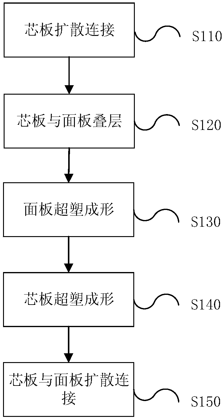
Hollow structure forming method
A hollow structure, superplastic forming technology, applied in the direction of forming tools, non-electric welding equipment, manufacturing tools, etc., can solve the problems of eliminating surface groove defects, complex process control, long production cycle, etc., to reduce the number of tests and cycles, Cost reduction and easy operation
- Summary
- Abstract
- Description
- Claims
- Application Information
AI Technical Summary
Problems solved by technology
Method used
Image

Examples
Embodiment Construction
[0026] The embodiments of the present invention will be described in further detail below in conjunction with the drawings and examples. The detailed description and drawings of the following embodiments are used to exemplarily illustrate the principles of the present invention, but cannot be used to limit the scope of the present invention, that is, the present invention is not limited to the described embodiments, without departing from the spirit of the present invention. The following covers any modification, replacement and improvement of parts, components and connection methods.
[0027] It should be noted that the embodiments in this application and the features in the embodiments can be combined with each other if there is no conflict. Hereinafter, the present application will be described in detail with reference to the drawings and in conjunction with embodiments.
[0028] In the aerospace integral structure, when the SPF / DB technology is used to prepare the four-layer h...
PUM
 Abstract
Description
Claims
Application Information