A vertical punching device for industrial boards that is convenient for chip removal

A technology of punching device and plate, applied in the direction of manufacturing tools, fixed drilling machines, wood processing appliances, etc., can solve the problems of easy damage of drill bits, inability to discharge wood chips, damage, etc., to prevent wood chips from splashing, facilitate centralized processing, and facilitate The effect of timely chip removal

Active Publication Date: 2021-11-05
ANHUI SHUORI PHOTOELECTRIC TECH
View PDF0 Cites 0 Cited by
  • Summary
  • Abstract
  • Description
  • Claims
  • Application Information

AI Technical Summary

Problems solved by technology

[0004] The purpose of the present invention is to provide a vertical punching device for industrial plates that is convenient for chip removal, which can solve the problem that the punching device cannot simultaneously limit and fix the plate horizontally and vertically, resulting in the stability of the plate when drilling Not strong, and not suitable for drilling boards of different widths and heights. It is relatively single, not strong in applicability, and cannot discharge wood chips well. Too much wood chips are easy to splash on the device parts, and it is easy to fix It causes damage, the accuracy of drilling is not high, the drill bit is easily damaged, and the wear between parts is more serious.

Method used


Image

  • A vertical punching device for industrial boards that is convenient for chip removal
  • A vertical punching device for industrial boards that is convenient for chip removal
  • A vertical punching device for industrial boards that is convenient for chip removal

Examples


Embodiment 1

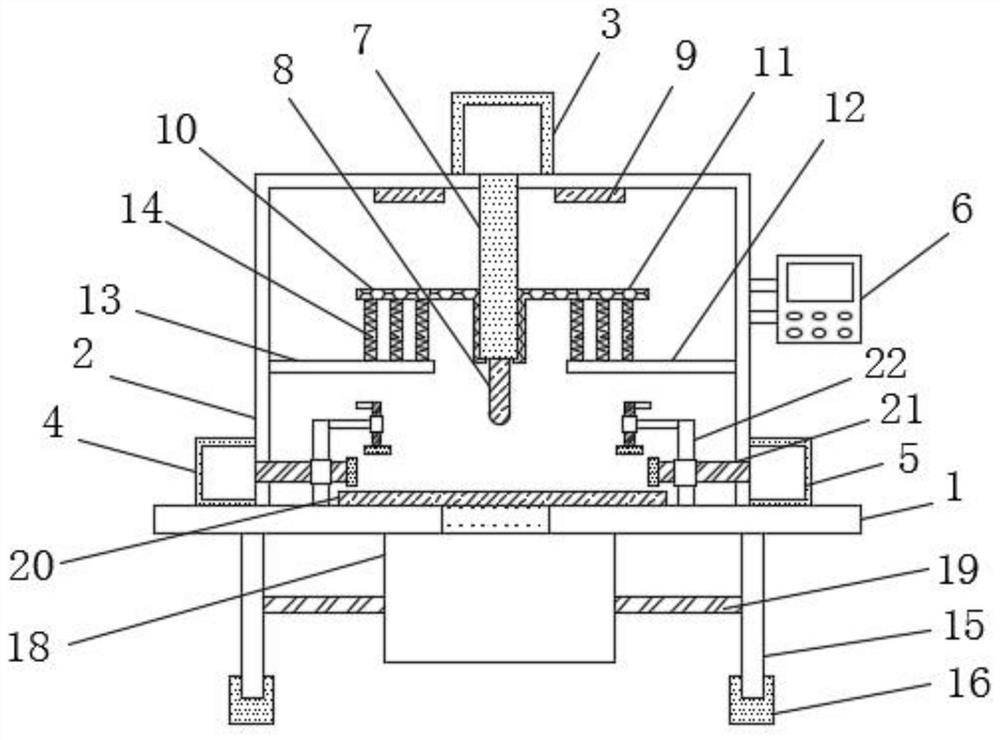
[0040] see Figure 1-2 As shown, a vertical punching device for industrial boards that is convenient for chip removal includes a workbench 1, and a device shell 2 is fixedly installed on the upper outer surface of the workbench 1, and the middle position of the upper end outer surface of the device shell 2 is A No. 1 cylinder 3 is installed, and the two sides of the device shell 2 are respectively installed with a No. 2 cylinder 4 and a No. 3 cylinder 5 near the bottom end. A control panel 6 is fixedly installed above the No. 3 cylinder 5. There is a No. 1 hydraulic telescopic rod 7 installed on the bottom surface of the cylinder 3 and located in the middle of the upper end of the device housing 2. The bottom end of the No. 1 hydraulic telescopic rod 7 is equipped with a drill bit 8, and the No. 1 hydraulic telescopic rod 7 is close to the upper end. Limiting baffles 9 are installed on both sides, and a No. 1 spring plate 10 and a No. 2 spring plate 11 are respectively install...

Embodiment 2

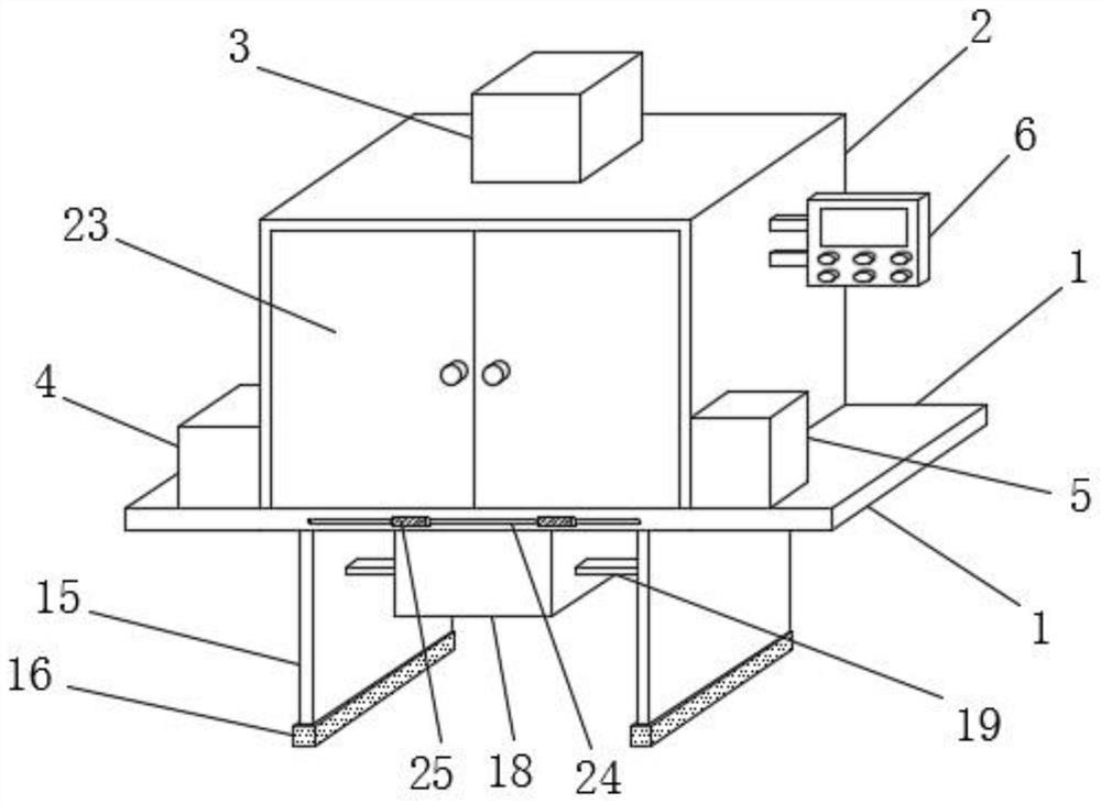
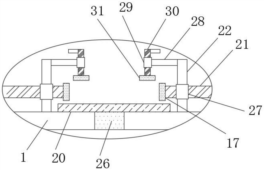
[0043] see Figure 3-4 As shown, the other end of the No. 2 hydraulic telescopic rod 21 is equipped with a transverse limit pad 17, and a sawdust outlet 26 is opened through the inner middle position of the workbench 1. The No. 2 hydraulic telescopic rod 21 and the column 22 A protective cover 27 is installed at the connection position of the vertical column 22, and a cross bar 28 is connected to the upper end of the column 22. An annular frame 29 is installed on the end of the horizontal bar 28 away from the column 22, and an adjusting bolt is slidably installed on the inner wall of the annular frame 29. 30, the bottom end of the adjustment bolt 30 is installed with a vertical limit block 31;

[0044] A fixed block 32 is fixedly installed in the middle position of the No. 1 hydraulic telescopic rod 7, and a light spring 33 is connected between the fixed block 32 and the top of the drill bit 8;

Embodiment 3

[0046] see Figure 5-8 As shown, the middle position of the upper outer surface of the buffer pad 20 is provided with a No. 2 slideway 34, and two sets of vertical slide bars 35 are installed in parallel sliding inside of the No. 2 slideway 34. The buffer pad 20 Slide rails 36 are provided on both sides of the inside of the slide rail 36, and the No. 1 slide plate 37 and the No. 2 slide plate 42 are slidably installed on the slide rail 36. The middle position of the No. 1 slide plate 37 and the No. 2 slide plate 42 is provided with a joint block 38, a chute 39 is opened on the inner side of the workbench 1, and two sets of horizontal sliding bars 40 are slidably installed in the chute 39, and the connecting block 38 is connected with the bottom end of the vertical sliding bar 35 A fixing bolt 41 is installed.

[0047] Preferably, the vertical slide bar 35 is vertically arranged and fixedly connected to the horizontal slide bar 40, and the vertical slide bar 35 is fixedly inst...


PUM


Abstract

The invention discloses a vertical punching device for industrial plates, which is convenient for chip removal. Cylinder, the No. 2 cylinder and No. 3 cylinder are respectively installed on both sides of the device casing near the bottom end, the control panel is fixedly installed above the No. 3 cylinder, and the bottom surface of the No. 1 cylinder is located in the device casing. A No. 1 hydraulic telescopic rod is installed in the middle position of the inner upper end of the slat; the invention discloses a vertical punching device for an industrial plate which is convenient for chip removal, which can limit and fix the plate horizontally and vertically, so that it has a relatively high performance when drilling. Good stability, suitable for drilling plates of different widths and heights, easy to discharge wood chips on the buffer pad in time, able to slowly drill the plate, higher drilling accuracy, and reduce energy consumption and wear between components.

Description

technical field [0001] The invention relates to a punching device, in particular to a vertical punching device for industrial plates which is convenient for chip removal. Background technique [0002] The punching device is an instrument for orderly drilling various objects, and the punching device is also a punching machine. According to the category, it can be divided into: pearl punching machine, laser punching machine, automatic punching machine, electric punching machine, manual punching machine, plastic bag punching machine, pneumatic punching machine and non-woven fabric punching machine, according to The number of holes can be divided into: single-hole punching machine, two-hole punching machine, three-hole punching machine and four-hole punching machine. With the continuous development of industry, the industrial punching device has been improved in structure and function, and has a wide application prospect, but the existing punching device still has certain short...

Claims


Application Information

Patent Timeline
Patent Type & Authority Patents(China)
IPC IPC(8): B27C3/00B27C3/02B27G3/00
CPCB27C3/00B27C3/02B27G3/00
Inventor 吴有军
Owner ANHUI SHUORI PHOTOELECTRIC TECH
Why Eureka
Try Eureka