Idle gear part of engine

An idler gear and engine technology, applied in the direction of gear transmission, belt/chain/gear, mechanical equipment, etc., can solve the problems of heavy weight, difficult assembly, narrow assembly space, etc., to achieve automatic mechanical production and reduce labor intensity of workers , the effect of simple assembly process

Pending Publication Date: 2019-01-18
GUANGXI YUCHAI MASCH CO LTD
View PDF0 Cites 0 Cited by
  • Summary
  • Abstract
  • Description
  • Claims
  • Application Information

AI Technical Summary

Problems solved by technology

[0005] When assembling traditional idler gear components, it is necessary to ensure that the marking points of the idler gear are aligned, and that the mounting hole of the idler gear shaft is aligned with the body, which is difficult to assemble, especially for heavy-duty engine gears, which are large in shape and heavy in weight Large, narrow assembly space and easily blocked marking points, only manual adjustment assembly, extremely low efficiency

Method used


Image

  • Idle gear part of engine
  • Idle gear part of engine
  • Idle gear part of engine

Examples


Embodiment Construction

[0023] The specific embodiments of the present invention will be described in detail below in conjunction with the accompanying drawings, but it should be understood that the protection scope of the present invention is not limited by the specific embodiments.

[0024] Unless expressly stated otherwise, throughout the specification and claims, the term "comprise" or variations thereof such as "includes" or "includes" and the like will be understood to include the stated elements or constituents, and not Other elements or other components are not excluded.

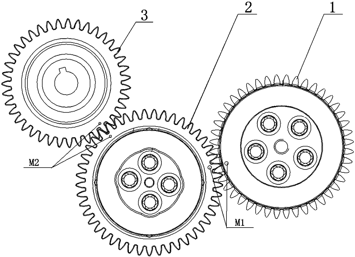
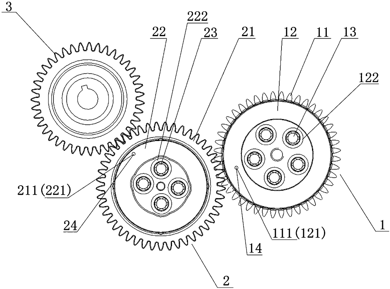
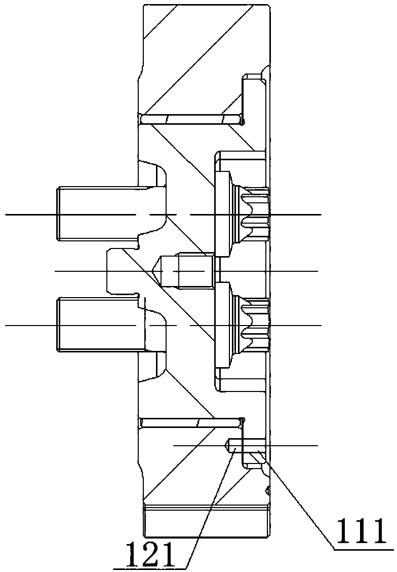
[0025] Such as Figure 2 to Figure 4 as shown, figure 2 is a structural schematic diagram of an idler gear part of an engine according to an embodiment of the present invention; image 3 is a side sectional structural schematic diagram of an intermediate idler gear of an engine idler gear assembly according to an embodiment of the present invention; Figure 4 is a side cross-sectional structural schematic diagram of an ...


PUM


Abstract

The invention discloses an idle gear part of an engine. The part is meshed with an oil pump gear, and the oil pump gear is fixed on an engine body. The idle gear part of the engine includes an intermediate inert gear and an oil pump inert gear. The intermediate inert gear is composed of a first inert gear, a first inert gear shaft and at least one first installation bolt, and the intermediate inert gear is fixed on the engine body; the oil pump inert gear is composed of a second inert gear, a second inert gear shaft and at least one second installation bolt. One side of the oil pump inert gearis meshed with the intermediate inert gear, the other side is meshed with the oil pump gear, and the oil pump gear is fixed on the engine body. The first inert gear is provided with a first positioning technology hole, the first inert gear shaft is provided with a second positioning technology hole, and the first positioning technology hole and the second positioning technology hole are same in diameter and coincides. Therefore, the idle gear part of the engine does not need to make a timing mark on the inert gear, the assembly is simple, and the production efficiency is high.

Description

technical field [0001] The invention relates to the field of engines, in particular to an engine idler gear component. Background technique [0002] The gear system driving the oil pump needs to control the angle between the oil pump cam and the engine crankshaft in order to ensure accurate fuel injection timing. Usually, a series of timing marks are arranged on the gear train for assembly. Due to the arrangement, the crankshaft cannot directly drive the oil pump, and there are several sets of idler gear parts in the middle for the transition, and the idler gear parts are generally composed of idler gears, idler gear shafts and mounting bolts, therefore, it is necessary to make a design on the idler gears during design. Timing marks to ensure that specified phasing requirements are met during assembly. [0003] When designing the current engine gear train, in order to ensure the correct phase, it is necessary to arrange timing marks on a series of gears that transmit power,...

Claims


Application Information

Patent Timeline
Patent Type & Authority Applications(China)
IPC IPC(8): F16H1/22
CPCF16H1/22
Inventor 廖升友余锦海覃壮革魏晓东向本杰谷峪
Owner GUANGXI YUCHAI MASCH CO LTD
Why Eureka
Try Eureka