Rotary kiln structure
A technology of rotary kiln and kiln head cover, applied in the direction of combustion method, combustion type, incinerator, etc., can solve problems such as affecting waste incineration
- Summary
- Abstract
- Description
- Claims
- Application Information
AI Technical Summary
Problems solved by technology
Method used
Image
Examples
Embodiment Construction
[0016] The following is a further detailed description through specific implementations:
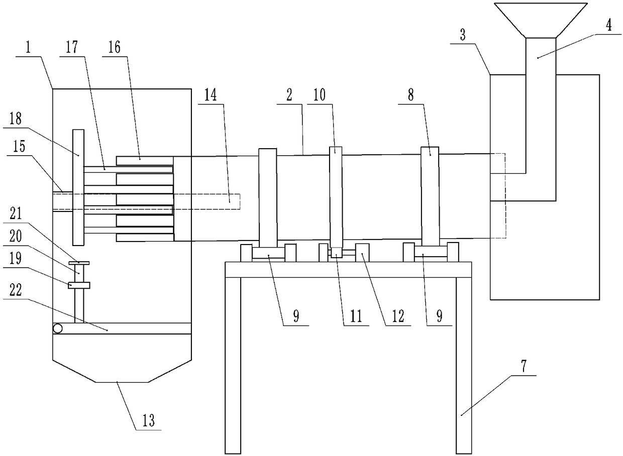
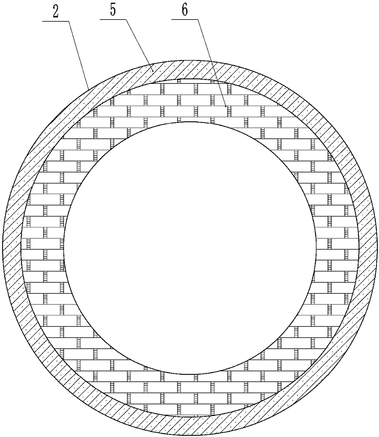
[0017] The reference signs in the drawings of the specification include: kiln head cover 1, cylinder body 2, kiln tail cover 3, conveying barrel 4, clay brick 5, chrome corundum brick 6, support frame 7, belt wheel 8, supporting wheel 9, Outer ring gear 10, gear 11, motor 12, slag outlet 13, incineration tube 14, sleeve 15, horizontal plate 16, ejector pin 17, cam 18, collar 19, push rod 20, push plate 21, baffle 22 .
[0018] As attached figure 1 As shown, the structure of the rotary kiln includes a support frame 7, a motor 12 and a cylinder body 2. The left end of the cylinder body 2 is provided with a rotary connecting kiln head cover 1, and the lower part of the kiln head cover 1 is provided with a slag outlet 13; the right end of the cylinder body 2 is provided The kiln end cover 3 is connected with rotation. Graphite gaskets are installed between the kiln head cover 1 and the kiln end ...
PUM
| Property | Measurement | Unit |
|---|---|---|
| Thickness | aaaaa | aaaaa |
| Thickness | aaaaa | aaaaa |
| Angle | aaaaa | aaaaa |
Abstract
Description
Claims
Application Information
 - R&D
- Intellectual Property
- Life Sciences
- Materials
- Tech Scout
- Unparalleled Data Quality
- Higher Quality Content
- 60% Fewer Hallucinations
Browse by: Latest US Patents, China's latest patents, Technical Efficacy Thesaurus, Application Domain, Technology Topic, Popular Technical Reports.
© 2025 PatSnap. All rights reserved.Legal|Privacy policy|Modern Slavery Act Transparency Statement|Sitemap|About US| Contact US: help@patsnap.com


