Method for implementing light pipe field array having predetermined characteristic

A light pipe field and array technology, which is applied in the field of tight focusing, can solve the problem of few researches on multi-segment hollow light pipes, and achieve the effect of simple method.

Active Publication Date: 2019-01-18
QUANZHOU NORMAL UNIV
View PDF7 Cites 5 Cited by
  • Summary
  • Abstract
  • Description
  • Claims
  • Application Information

AI Technical Summary

Problems solved by technology

However, little research has been done on how to generate mul

Method used


Image

  • Method for implementing light pipe field array having predetermined characteristic
  • Method for implementing light pipe field array having predetermined characteristic
  • Method for implementing light pipe field array having predetermined characteristic

Examples


Embodiment Construction

[0033] The technical solution of the present invention will be specifically described below in conjunction with the accompanying drawings.

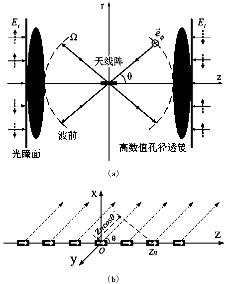
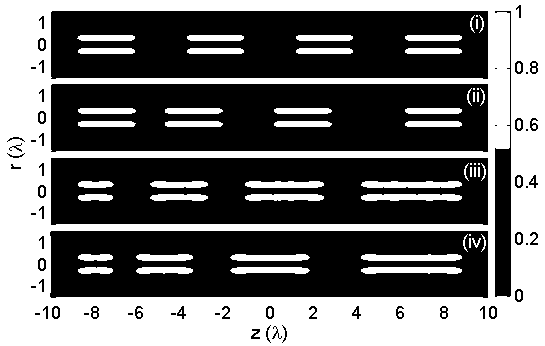
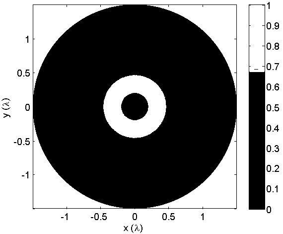
[0034] The invention provides a method for realizing a light pipe field array with predetermined characteristics. By reversely inverting the radiation field of a collinear antenna array composed of uniform magnetic current line source array elements, a hollow light pipe array is generated in the focal area. The specific implementation of this method is as follows:

[0035] First, it is assumed that a virtual antenna array is placed at the focal center of a 4π high numerical aperture (NA) lens along the optical axis;

[0036] Then, the field radiated from the virtual antenna array is completely collected by two high numerical aperture (NA) lenses and transmitted from image space to the pupil plane of the lenses; here, the field distribution on the pupil plane can be obtained by solving the inverse problem If the lens obeys the Helmholt...


PUM


Abstract

The invention relates to a method for implementing a light pipe field array having predetermined characteristic. According to the method, a hollow light pipe array is achieved by reversely rotating aradiation field of an isotropic collinear magnetic current antenna array arranged at a focus region. A simulation example shows that the implemented hollow light pipe is in pure azimuthal polarization, the light intensity distribution within the whole focal depth range is hardly maintained unchanged, and the shape and the position of the hollow light pipe are respectively dependent on an element factor and an array factor. The light pipe array having predetermined property, implemented by the method, can be expected to be used for the fields of multi-particle capturing and control, multi-particle processing and photoetching and the like.

Description

technical field [0001] The present invention relates to the tight focusing technology of cylindrical vector light beams, in particular to a method for realizing a hollow light pipe array in a 4π focal region by using the radiation pattern of a collinear magnetic current antenna array through time inversion, especially a method for realizing a hollow light pipe array with a predetermined Properties of light pipe field array methods. Background technique [0002] The hollow light pipe formed by the cylindrical vector beam under the focus of a high numerical aperture (NA, Numerical Aperture) lens, because of its zero intensity distribution along the central axis, has great potential in the fields of particle trapping, micromanipulation, lithography, and optical microscopy. important application, so it has been extensively studied. [0003] Researchers have theoretically and experimentally proposed many methods for generating and manipulating hollow light pipes. For example, J...

Claims


Application Information

Patent Timeline
IPC IPC(8): G02F1/35H01Q19/06H01Q21/00H01Q21/08
CPCG02F1/3511H01Q19/062H01Q21/0087H01Q21/08
Inventor 余燕忠贾蕾
Owner QUANZHOU NORMAL UNIV
Why Eureka
Try Eureka