
Motor control system and method for water treatment engineering

A technology for motor control and water treatment, applied in general control systems, control/regulation systems, program control, etc., can solve the problem that the automatic control system cannot be restored to normal, increase the labor operation cost of the sewage plant, and the control system is disturbed and malfunctioned. Reliable operation and compliance Emissions etc.

Inactive Publication Date: 2019-01-18
CSD BEIJING E P DEV CO LTD
View PDF9 Cites 2 Cited by
  • Summary
  • Abstract
  • Description
  • Claims
  • Application Information

AI Technical Summary

Problems solved by technology

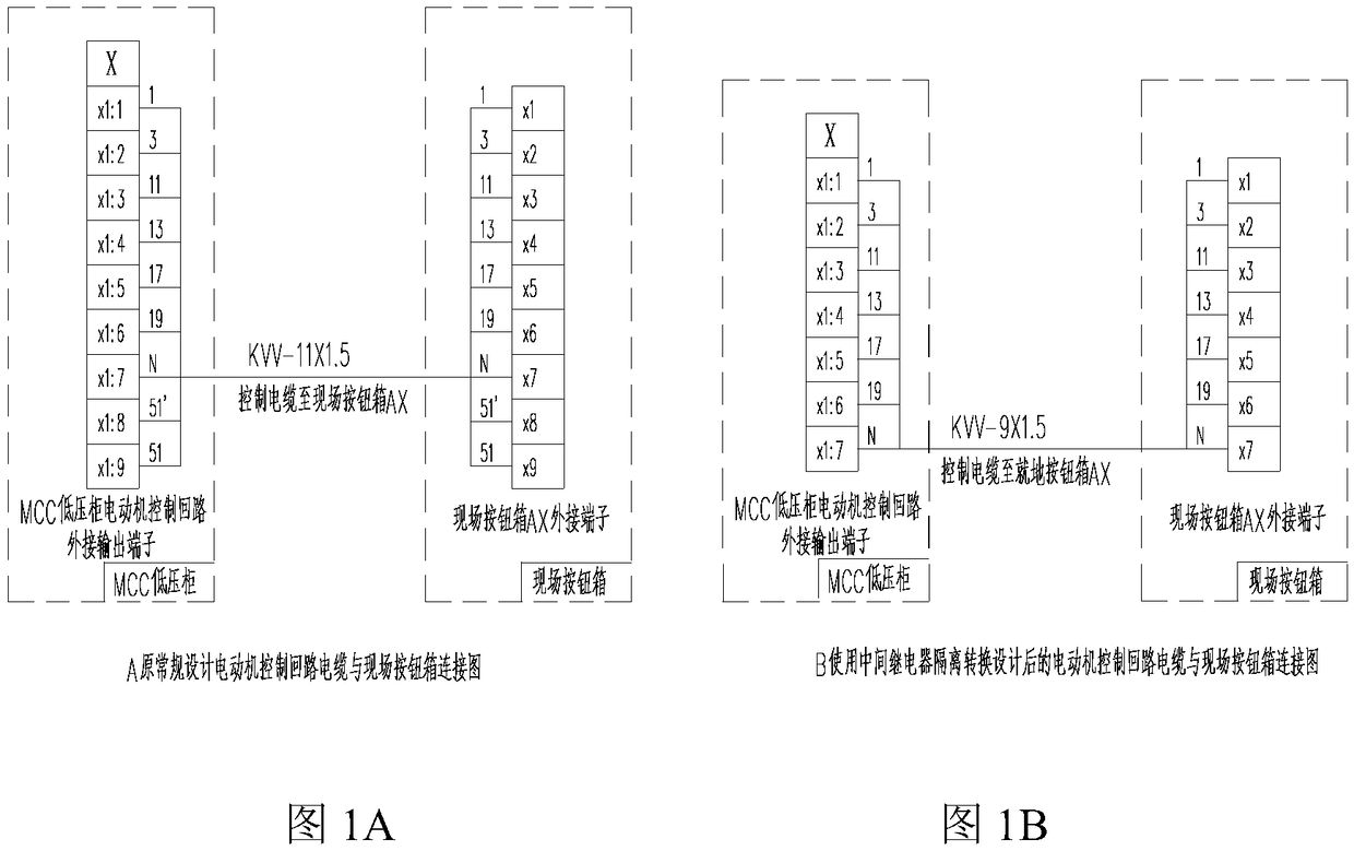
[0005] The manual / automatic signal passes through the motor control cable connected to the field button box. According to the design specifications, it is usually designed that the motor control cable and the power cable are laid in the same cable trench or bridge, so that during the transmission process, the motor control cable has many problems due to the laying environment. Various current or voltage changes (inverter use, load changes, equipment start-stop, etc.) and other complex electromagnetic environments with strong interference will generate induction electricity, and the electromagnetic interference will react to the control system cabinet, causing some automatic control signal circuits to induce voltage or It can reach more than 100 volts of AC, causing the control system to be disordered, malfunctioning or unable to work normally, affecting its reliable operation and standard discharge. The automatic control system is disordered or cannot return to normal for a long time, which will force the sewage plant to enter the manual operation control mode, increasing the sewage plant. Labor cost

Method used


Image

  • Motor control system and method for water treatment engineering
  • Motor control system and method for water treatment engineering
  • Motor control system and method for water treatment engineering

Examples


Embodiment Construction

[0030] The objects and functions of the present invention and methods for achieving the objects and functions will be clarified by referring to the exemplary embodiments. However, the present invention is not limited to the exemplary embodiments disclosed below; it can be implemented in various forms. The essence of the description is only to help those skilled in the relevant art comprehensively understand the specific details of the present invention.

[0031] Hereinafter, embodiments of the present invention will be described with reference to the accompanying drawings. In the drawings, the same reference numerals represent the same or similar components, or the same or similar steps.

[0032] In the motor control mode of traditional water treatment engineering design, the manual / automatic DI signal of the automatic control system is taken from a pair of dedicated contacts of the manual / automatic switch of the field button box (field operation box), that is, the manual / aut...


PUM


Abstract

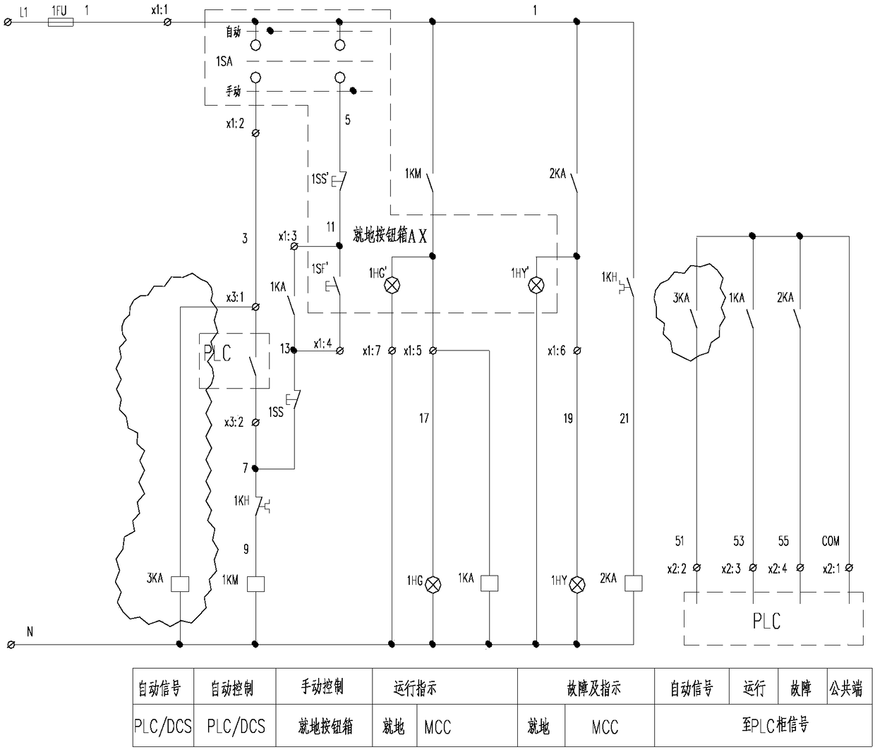
The invention provides a motor control system for water treatment engineering. The motor control system comprises an MCC low-voltage cabinet, a PLC / DCS controller and a spot operation box, wherein thePLC / DCS controller comprises a signal input module and a signal output module; the signal input module is connected with the MCC low-voltage cabinet; the motor control system furthermore comprises acontactor which is located on the MCC low-voltage cabinet and is used for controlling the ON / OFF of a motor main circuit; a coil of the contactor is connected with a motor control loop and is controlled through the signal output module of the PLC / DCS controller; an intermediate relay is connected with two ends of a coil loop of the contactor in parallel; when a manual / automatic switching switch isswitched to a contact corresponding to an automatic control manner, the intermediate relay is closed; the intermediate relay is connected with the signal input module of the PLC / DCS controller; and an opening or closing state signal of the intermediate relay serves as an automatic control manner signal and is transferred to a weak current digital input end of the signal input module of the PLC / DCS controller.

Description

technical field [0001] The invention relates to the field of equipment control in the field of water treatment, in particular to a motor control system and a control method for water treatment engineering. Background technique [0002] In the design of water treatment engineering, in order to meet the standard discharge, the process profession needs to configure a large number of various process equipment to complete the treatment functions of sewage (waste) water treatment such as lifting, backflow, stirring, blast aeration, dosing, and sludge disposal. Usually, multiple types of motors such as electric motors are configured as a transmission power source in a set. [0003] According to the requirements of the process control conditions, the electrical major usually adopts two control modes of manual / automatic for the motor and realizes the function through the corresponding control circuit. The on-site button box (or operation column) is set on the equipment site to comple...

Claims


Application Information

Patent Timeline
IPC IPC(8): G05B19/05
CPCG05B19/054G05B2219/1184
Inventor 张彦
Owner CSD BEIJING E P DEV CO LTD
Learn More