

A battery management system and circuit for charging and discharging a battery pack
A battery management system, battery pack technology, applied in battery circuit devices, different battery charging, circuit devices, etc., can solve problems such as low charging and discharging efficiency, and achieve the effect of improving charging and discharging efficiency, and taking into account both safety and efficiency.
- Summary
- Abstract
- Description
- Claims
- Application Information
AI Technical Summary
Problems solved by technology
Method used
Image

Examples
example 1
[0059] Example 1. Battery management system BMS and charging and discharging circuit
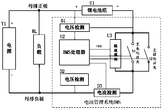
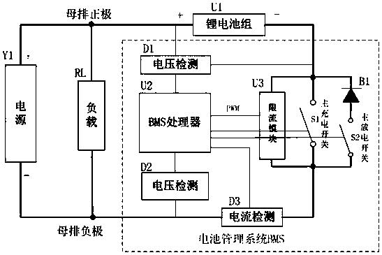
[0060] image 3 It is a charging and discharging circuit for a battery pack according to an embodiment of the present invention Figure three .
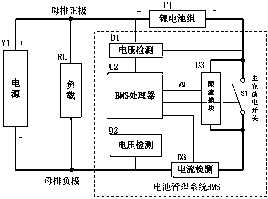
[0061] like image 3 As shown, the current limiting module U3 is connected in parallel to both ends of the main circuit switch S1 to form a switch part, and the switch is controlled by the BMS processor. The switch part is connected in series with the battery pack U1 and the power supply Y1 to form a battery charging circuit; when the power supply Y1 is powered off, the switch part is connected in series with the battery pack and the load RL to form a battery discharge circuit. The battery management system (BMS) is used to detect and sample voltage, current, temperature, etc., and to control and manage the safe and reliable operation of lithium battery packs. It mainly includes but is not limited to the following parts (in the dashed box): BMS ...
example 2
[0075] Example 2. A method for charging and discharging a battery pack using the circuit in Example 1.
[0076] Step 1, BMS processor U2 calculates and judges whether there is a fault or protection alarm in the system before battery charging starts;
[0077] If not, first close the main discharge switch S2 and connect the main discharge circuit to ensure the ability to discharge at any time. Step 2, the BMS detects the power supply voltage Uy in real time through the voltage detection module D2, and the voltage detection module D1 detects the battery pack voltage Ub in real time;
[0078] Step 3, the BMS processor U2 controls the charging mode by calculating the pressure difference ΔV between Uy and Ub and the agreed threshold U0.
[0079] (1) If the pressure difference △V (△V=Uy-Ub) between Uy and Ub is greater than the agreed threshold U0, that is, △V>U0, there is a risk of charging overcurrent if the pressure difference is too large. At this time, the BMS processor U2 cont...
example 3
[0085] Example 3, the power supply Y1 and the load RL are used to describe the application scenario of the present invention. The battery pack is used as a backup power supply for supplying power to the load RL when the power supply Y1 is powered off. The BMS processor is controlled and managed by the battery management system BMS The core component of the main circuit switch is connected in parallel with the current limiting module, and the switch state is controlled by the BMS processor. The method provided by Example 3 may include the following steps:
[0086] Step 1, setting the pressure difference threshold U0 and the current protection threshold Imax parameter size in the BMS;
[0087] Step 2, after the BMS processor U2 is powered on and initialized, it detects the system protection mechanism and fault;
PUM
 Abstract
Description
Claims
Application Information