Automatic loading and unloading device of digital controlled lathe

A technology of automatic loading and unloading, CNC lathe, applied in the direction of automatic in/out of workpieces, metal processing mechanical parts, metal processing, etc., can solve the problems of low work efficiency, low work efficiency, large floor space, etc. The effect of production auxiliary time, space saving and compact layout

Pending Publication Date: 2019-01-22
LIAONING UNIVERSITY OF TECHNOLOGY
View PDF8 Cites 6 Cited by
  • Summary
  • Abstract
  • Description
  • Claims
  • Application Information

AI Technical Summary

Problems solved by technology

[0003] At present, the existing automatic loading and unloading devices for CNC lathes do not have high requirements for the working efficiency of the loading and unloading devices. Usually, during the working period of the loading and unloading devices, the CNC machine tool stops working and waits for the completion of loading and unloading before continuing to work, resulting in a greatly reduced work efficiency.
In addition, the existing automatic loading and unloading devices for CNC lathes are usually composed of two parts: the loading device and the unloading device.

Method used


Image

  • Automatic loading and unloading device of digital controlled lathe
  • Automatic loading and unloading device of digital controlled lathe
  • Automatic loading and unloading device of digital controlled lathe

Examples


Embodiment 1

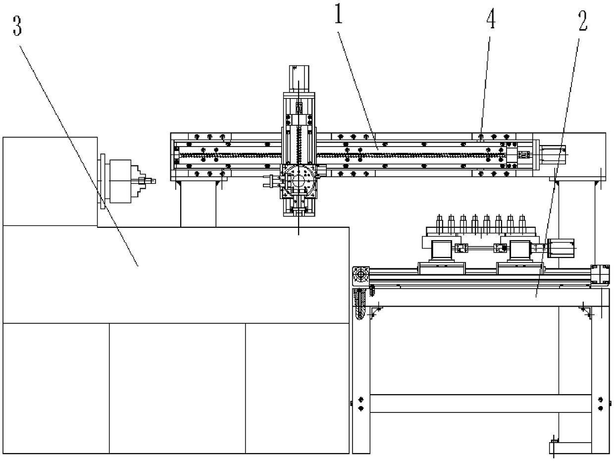
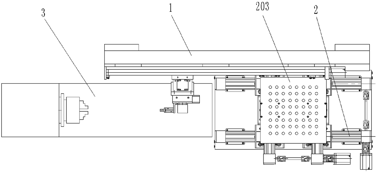
[0020] Such as Figure 1-Figure 4 As shown, an automatic loading and unloading device for a CNC lathe, including a manipulator system 1 and a loading tray system 2, a CNC lathe 3 is provided at one end of the loading tray system 2, and a manipulator system 1 is provided directly opposite the CNC lathe 3 and the loading tray system 2 .

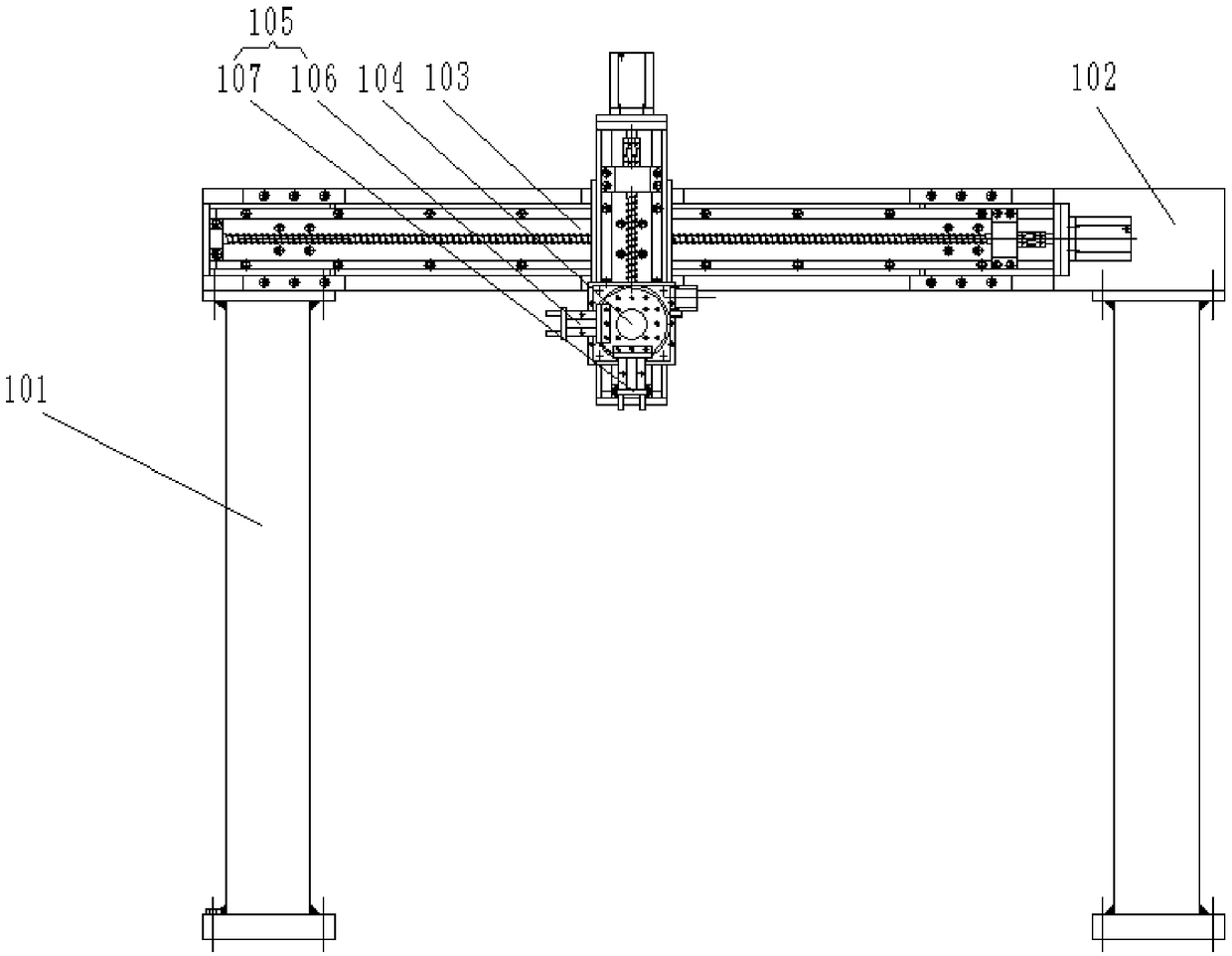
[0021] The manipulator system 1 includes a beam frame 101, the top of the two beam frames 101 is provided with a beam 102, and the front side wall of the beam 102 is provided with a cross-shaped screw slide module 103, and the cross-shaped screw slide module 103 passes through The horizontal slide table and the front end of the beam 102 are fixedly installed, and the ends of the cross-shaped screw slide table module 103 vertical slide table and the horizontal slide table are all provided with limit switches 4, and the setting of the limit switch 4 ensures that the vertical slide table or the horizontal slide table The slide table will not exce...


PUM


Abstract

The invention provides an automatic loading and unloading device of a digital controlled lathe, and belongs to the technical field of mechanical manufacturing equipment. The automatic loading and unloading device of the digital controlled lathe comprises a manipulator system and a charging tray system, wherein the digital controlled lathe is arranged on one side of the charging tray system; and the manipulator system is arranged on the surface, which faces the charging tray system, of the digital controlled lathe. By the automatic loading and unloading device of the digital controlled lathe, during loading and unloading, continuous loading and unloading in a machining process of the digital controlled lathe can be realized through two gas claws of the manipulator system, the production auxiliary time is greatly shortened, and the production efficiency is improved effectively; according to the automatic loading and unloading device of the digital controlled lathe, the same system deviceis formed by the manipulator system and the charging tray system; and the automatic loading and unloading device of the digital controlled lathe is simple in structure, compact in overall arrangementand low in cost, and the occupied area is saved effectively.

Description

technical field [0001] The invention belongs to the technical field of mechanical manufacturing equipment, and in particular relates to an automatic loading and unloading device for a numerically controlled lathe. Background technique [0002] The machine tool loading and unloading device is an automatic or semi-automatic mechanical device that sends the workpiece to be processed to the processing position on the machine tool and removes the processed workpiece from the processing position. According to the degree of automation, there are two types of loading and unloading devices for machine tools: manual loading and unloading and automatic loading and unloading devices. The manual loading and unloading device is implemented by manual operation, which often takes more time and consumes physical strength. The automatic loading and unloading device adopts various automatic loading and unloading devices, which mechanizes the loading and unloading process, further shortens the...

Claims


Application Information

Patent Timeline
Patent Type & Authority Applications(China)
IPC IPC(8): B23B15/00
CPCB23Q7/04B23Q2707/003
Inventor 王宇钢
Owner LIAONING UNIVERSITY OF TECHNOLOGY
Why Eureka
Try Eureka