
Die holding quenching device for railway bearing inner ring

A technology for railway bearings and quenching devices, which is applied to quenching devices, manufacturing tools, heat treatment equipment, etc., can solve the problems of prolonged production auxiliary time, narrow space, difficult adjustment, etc., and achieve excellent quenching quality, reasonable structure, and improved working environment. Effect

Active Publication Date: 2016-08-24
NINGXIA MACHINERY RES INST
View PDF8 Cites 0 Cited by
  • Summary
  • Abstract
  • Description
  • Claims
  • Application Information

AI Technical Summary

Problems solved by technology

Since the quenching device has an upper plate, a movable plate, and a middle partition to divide the quenching oil tank into upper and lower cavities, and the quenching mold is fixed on the partition, although the quenching efficiency and quality are guaranteed, the mold needs to be removed first Putting on the platen, and then disassembling and assembling the mold in the upper cavity, due to the narrow space, it is very inconvenient, difficult to adjust, and the auxiliary production time is lengthened

Method used


Image

  • Die holding quenching device for railway bearing inner ring

Examples


Embodiment Construction

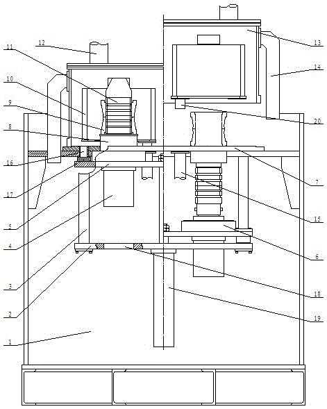
[0019] In the figure: 1—oil tank, 2—fixed plate, 3—guiding column, 4—mold cylinder, 5—supporting plate, 6—mold seat, 7—workbench, 8—workpiece supporting seat, 9—workpiece to be quenched, 10 - fuel injection ring, 11 - quenching mold, 12 - exhaust pipe, 13 - quenching oil cover, 14 - overflow pipe, 15 - oil inlet pipe, 16 - oil drain hole, 17 - gasket, 18 - mold cylinder hole, 19—supporting plate oil cylinder, 20 oil inlets.

[0020] Such as figure 1 As shown, the left side of the center line is the quenching station during the quenching process, and the right side of the center line is the pick-and-place workpiece station during the quenching process. The workbench 7 is horizontally installed in the oil tank 1, the guide column 3 is fixed on the lower plane of the workbench, the fixed plate 2 is installed at the lower end of the guide column, and the bracket that can move up and down along the guide column is installed between the fixed plate and the workbench. Plate 5, a su...


PUM


Abstract

The invention relates to a quenching device, and particularly to a railway bearing inner race mold retaining quenching device. The device comprises an oil tank, a worktable mounted inside the oil tank, a quenching mold mounted on the worktable and an quenching oil cover mounted at the upper part of the oil tank, and is characterized in that a fixing plate, a guiding rod and a supporting plate form an overall frame below the worktable; the quenching mold is mounted on the supporting plate; the quenching mold moves up to be inserted into an inner hole of a quenched workpiece and is used for implementing a quenching process in a closed quenching space formed by the quenching oil cover and the worktable. The quenching mold can move up to the surface of the worktable, so the mold is quite convenient, safe, clean and rapid to install and regulate, and the mold installation and regulation time is greatly shortened; compared with the prior art, the device can be used for reducing the production assistance time by more than 80%; meanwhile, no oil liquid overflows during the quenching process, and the device is environmentally friendly and quite applicable to ancillary use of large-batch thermal treatment production lines.

Description

technical field [0001] The invention relates to a quenching device, in particular to a quenching device for retaining a mold of the inner ring of a railway bearing. Background technique [0002] Quenching of the inner and outer rings of railway bearings is a key process, and the quality of quenching is one of the core processes of bearing manufacturing quality, which is closely related to the use status and service life of the bearing. The technology of adopting special quenching equipment and mold holding quenching is an emerging process in recent years. The applicant applied for the invention patent "Quenching Equipment for Inner and Outer Rings of Railway Bearings" ZL200610076933.4, and the invention patent "Hydraulic pressure for parts of conical inner hole rings" Stripping Fixed Quenching Die" ZL200620112482.6, "Collar Inner Hole Snare Parts Quenching Device" ZL200620112480.1, have been used in dozens of production lines of various domestic enterprises, making the heat t...

Claims


Application Information

Patent Timeline
Patent Type & Authority Patents(China)
IPC IPC(8): C21D1/62C21D9/40
CPCC21D1/62C21D9/40
Inventor 王国升张光荣王淑芳陈燕斌
Owner NINGXIA MACHINERY RES INST
Learn More