A catalyst automatic coating device for honeycomb exhaust pipe

An automatic coating and exhaust pipe technology, which is applied to the device and coating of the surface coating liquid, can solve the problem that the slurry flow rate and pressure cannot be well controlled, the slurry flow rate and pressure are not easy to be controlled, and the coating Overcoming problems such as quality control is not easy to achieve the effect of shortening production auxiliary time, reducing manpower and raw material consumption, and eliminating the influence of human operation factors

Active Publication Date: 2016-03-30
GUILIN UNIV OF ELECTRONIC TECH
View PDF6 Cites 0 Cited by
  • Summary
  • Abstract
  • Description
  • Claims
  • Application Information

AI Technical Summary

Problems solved by technology

[0004] The previous extensive production method represented by manual operation can no longer meet the needs of the market, quantitative and segmental coating is the general trend; for this reason, it is particularly necessary to develop a set of special equipment suitable for the above coating process
[0005] Just as the patent of publication number CN103240131A provides a simple coating machine for honeycomb ceramic carrier catalyst, which can realize efficient coating catalyst on honeycomb ceramic carrier, but the coating process is not carried out in a sealed environment, the slurry is easily polluted, and the operator It can affect health due to inhalation of atomized slurry, and the flow velocity and pressure of the slurry cannot be well controlled. The coating effect of the device of this invention is limited; a kind of carrier catalyst slurry provided by the patent of publication number CN101301645A The automatic coating machine can automatically coat the catalyst on cordierite honeycomb ceramics instead of manual operation. The coating process is carried out in a sealed environment, which is relatively safe and has high production efficiency. However, the sealing effect during the coating process is not good. The slurry flow rate and pressure are not easy to control, which in turn makes the coating quality difficult to control

Method used


Image

  • A catalyst automatic coating device for honeycomb exhaust pipe
  • A catalyst automatic coating device for honeycomb exhaust pipe
  • A catalyst automatic coating device for honeycomb exhaust pipe

Examples


Embodiment Construction

[0021] The present invention will be further described below in conjunction with the accompanying drawings and embodiments.

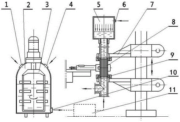
[0022] An automatic catalyst coating device for a honeycomb exhaust pipe, which consists of three parts: a material storage system, a pressure control system and a quick interface device.

[0023] The material storage system is mainly composed of a storage bin 2 and an agitator 3; the storage bin 2 stores the catalyst, and its upper part is provided with a feeding port 4 and a paint return port 1, and the lower part is provided with a discharge port 10, and its material is stainless steel; the material The supplementary pipe 16 is connected to the feeding port 4; the agitator 3 driven by a geared motor is arranged inside the storage bin 2, which ensures the real-time uniformity of the slurry (liquid) fluid and lays the foundation for the stability of the coating process.

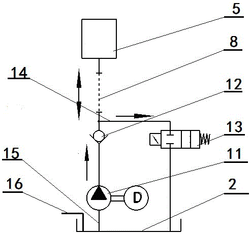
[0024] The pressure control system is mainly composed of a quantitative injection...


PUM


Abstract

The invention discloses an automatic coating device of a honeycomb exhaust pipe catalyst. The automatic coating device is composed of a material storage system, a pressure control system and a rapid interface device; the material storage system is mainly composed of a storage cabin and a stirrer; the pressure control system is mainly composed of a quantitative injection pump, a discharging pipe, a one-way valve, an electromagnetic valve, a backflow pipe and a pressure-retaining cabin; and the rapid interface device is mainly composed of a rapid joint mechanism, a double-upright-post frame, a stress-applying lever system, a sealing base assembly and a cylinder. By means of application of the automatic coating device of the honeycomb exhaust pipe catalyst disclosed by the invention, constancy and homogeneity of the coating amounts of coatings are ensured; the product quality accords with enterprise standard requirements; the labour intensity of first-line operators is greatly lightened; and the production efficiency is effectively increased.

Description

technical field [0001] The invention relates to the field of auto parts manufacturing, in particular to a catalyst automatic coating device for honeycomb exhaust pipes. Background technique [0002] Although the fuel supply of today's gasoline engines generally adopts the multi-point EFI technology outside the cylinder, the precision of oil and gas ratio has been greatly improved, and the combustion efficiency has been gradually improved; however, due to the high speed of modern engines, it is very difficult to completely purify the exhaust gas directly in the machine. It is still a worldwide problem, and an important way to reduce emissions is through the secondary treatment of exhaust gas outside the cylinder. The three-way catalytic conversion device is one of the most mature out-of-cylinder exhaust gas treatment methods for gasoline engines at present: when the exhaust gas passes through the honeycomb pipe section in the exhaust gas pipeline, under the action of the cata...

Claims


Application Information

Patent Timeline
Patent Type & Authority Patents(China)
IPC IPC(8): B05C7/04B05C11/10
Inventor 唐焱钱龙飞张斌高鹏陈金龙高波蒋占四高吟刘俊杰
Owner GUILIN UNIV OF ELECTRONIC TECH
Why Eureka
Try Eureka