Valve air pressure test device
A gas pressure test and valve technology, used in measuring devices, fluid tightness testing, and machine/structural component testing. , the effect of avoiding point contact or line contact
Active Publication Date: 2019-01-22
CHINA NUCLEAR IND 23 CONSTR
View PDF8 Cites 1 Cited by
- Summary
- Abstract
- Description
- Claims
- Application Information
AI Technical Summary
Problems solved by technology
In order to solve the problems of damage to the groove and unstable sealing when using the existing method to seal the valve port of a valve with a welded groove, the present invention proposes a valve air pressure test device
Method used
View moreImage
Smart ImageViewing Examples
Examples
Embodiment Construction
Login to View More PUM
 Abstract
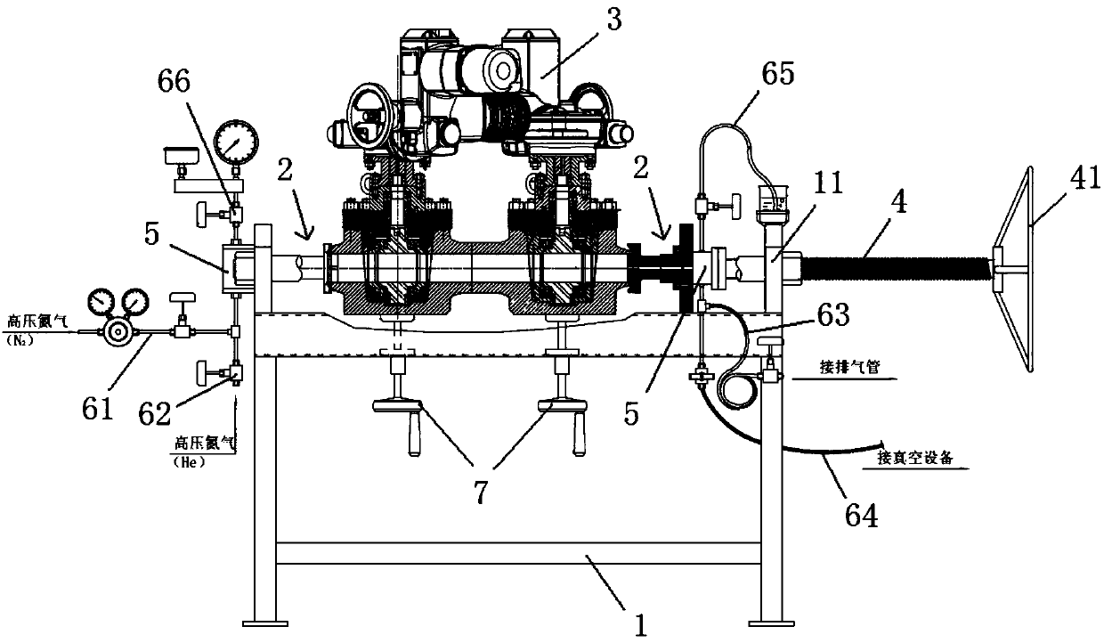
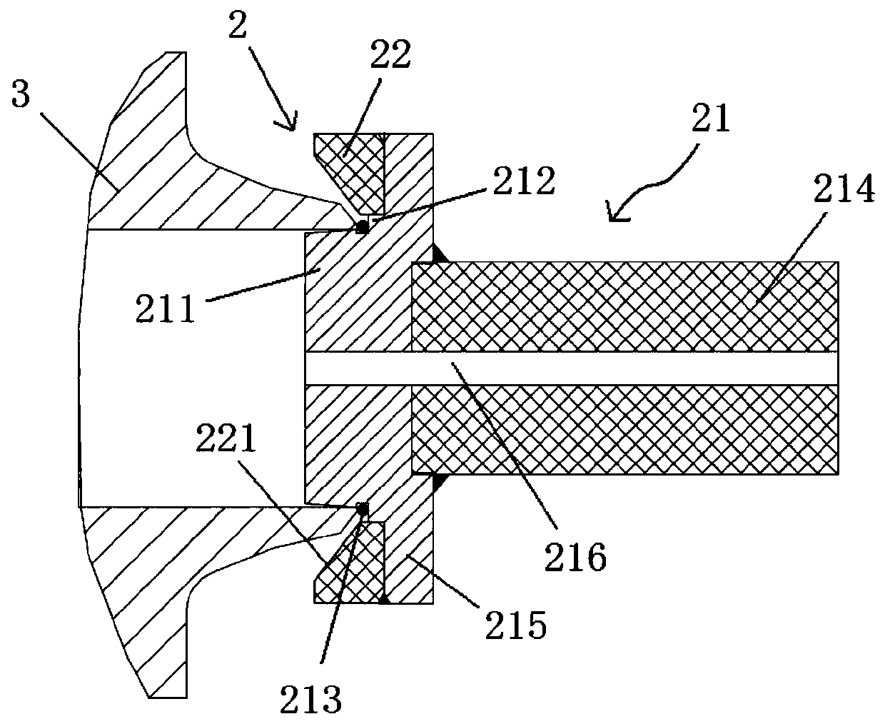
The invention belongs to the technical field of valve air pressure test equipment. Aiming at solving the problems that a groove is destroyed and sealing is instable when end face sealing is performedon a welding groove type valve by adopting an existing manner, the invention discloses a valve air pressure test device. The valve air pressure test device comprises a support frame and sealing components; the support frame is provided with two sealing components, and the two sealing components are oppositely arranged at intervals along the same horizontal direction; each sealing component comprises a gland and a support ring; each gland is of a step structure and comprises a first step, a second step and a sealing element, the first step stretches into a port of a valve and performs location,the outer diameter of the second step is larger than the outer diameter of the first step, and the sealing element is located at a position where the first step and the second step are connected; andone end face of each support ring is an inclined plane, an inclination angle is equal to an angle of a groove, each support ring sheathes the corresponding second step, and each inclined plane keepsparallel correspondence with an oblique plane of the groove. The valve air pressure test device disclosed by the invention seals the end face of the valve and can protect the groove and guarantee sealing stability.
Description
technical field The invention belongs to the technical field of air pressure test equipment for valves, and in particular relates to an air pressure test device for valves with welded grooves on the valve opening. Background technique The high-temperature gas-cooled reactor is an advanced nuclear energy technology with the characteristics of the fourth generation. Helium is used as the primary circuit coolant, and the nuclear fuel of the high-temperature reactor uses spherical ceramic-coated fuel and is driven by helium to realize the high-temperature gas-cooled reactor nuclear power plant demonstration The project (HTR-PM) does not stop fuel loading, unloading and circulation operation, so some pipelines, valves and online components in the high temperature reactor process system need to work under the high temperature and high pressure helium atmosphere. Among them, in order to ensure the sealing reliability of the valve during the working process, it is necessary to carry...
Claims
Login to View More Application Information
Patent Timeline
 Patent Type & Authority Applications(China)
IPC IPC(8): G01M3/28
CPCG01M3/2876
Inventor 郑艳奇高国新康增保郑佳孙朝朋杨会敏田野陈宏富刘磊
Owner CHINA NUCLEAR IND 23 CONSTR
Features
- R&D
- Intellectual Property
- Life Sciences
- Materials
- Tech Scout
- Unparalleled Data Quality
- Higher Quality Content
- 60% Fewer Hallucinations
Learn More Browse by: Latest US Patents, China's latest patents, Technical Efficacy Thesaurus, Application Domain, Technology Topic, Popular Technical Reports.
© 2025 PatSnap. All rights reserved.Legal|Privacy policy|Modern Slavery Act Transparency Statement|Sitemap|About US| Contact US: help@patsnap.com


