
Die-cutting machine for battery production

A die-cutting machine and battery technology, applied in metal processing, etc., can solve problems such as falling on the conveyor belt, contact with dust, and affecting the quality of battery pole pieces, so as to improve convenience and safety, ensure quality, and improve work. efficiency effect

Inactive Publication Date: 2019-01-25
江西尚立动力科技有限公司
View PDF5 Cites 2 Cited by
  • Summary
  • Abstract
  • Description
  • Claims
  • Application Information

AI Technical Summary

Problems solved by technology

Many processes are required in the production process of lithium electronics. After coating, the battery pole piece needs to be shaped by a die-cutting machine, and the battery pole piece is cut into a fixed shape of the battery. The coil material discharge of the pole piece is generally controlled by a photoelectric switch. , automatically and synchronously unwinding according to the forming length, the pole piece coil is then sent to the conveyor belt, and the pole piece coil is in contact with the conveyor belt. Since the conveyor belt rotates around the die-cutting machine up and down, during the rotation process, it will inevitably come into contact with Dust, or other impurities fall on the conveyor belt. When the pole piece coil is in contact with the conveyor belt, the impurities on the conveyor belt will be adsorbed on the battery pole piece, which will affect the quality of the battery pole piece, thereby affecting the quality of the battery product

Method used


Image

  • Die-cutting machine for battery production
  • Die-cutting machine for battery production
  • Die-cutting machine for battery production

Examples


Embodiment Construction

[0020] The present invention will be described in further detail below in conjunction with the accompanying drawings and specific embodiments.

[0021] Such as figure 1 , figure 2 , image 3 and Figure 4 shown;

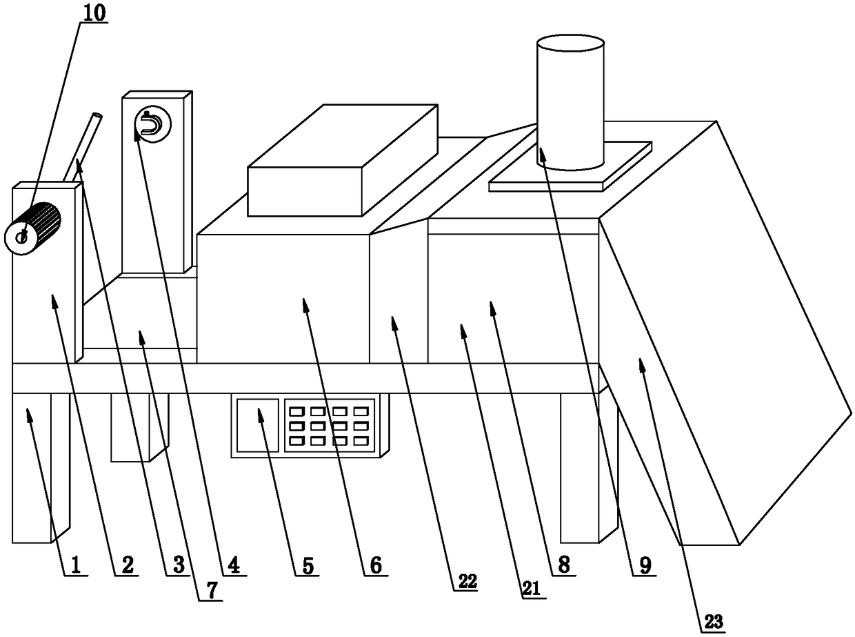
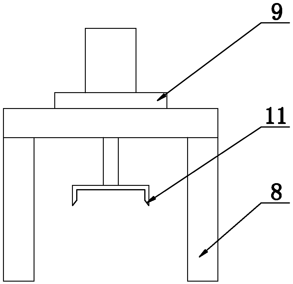
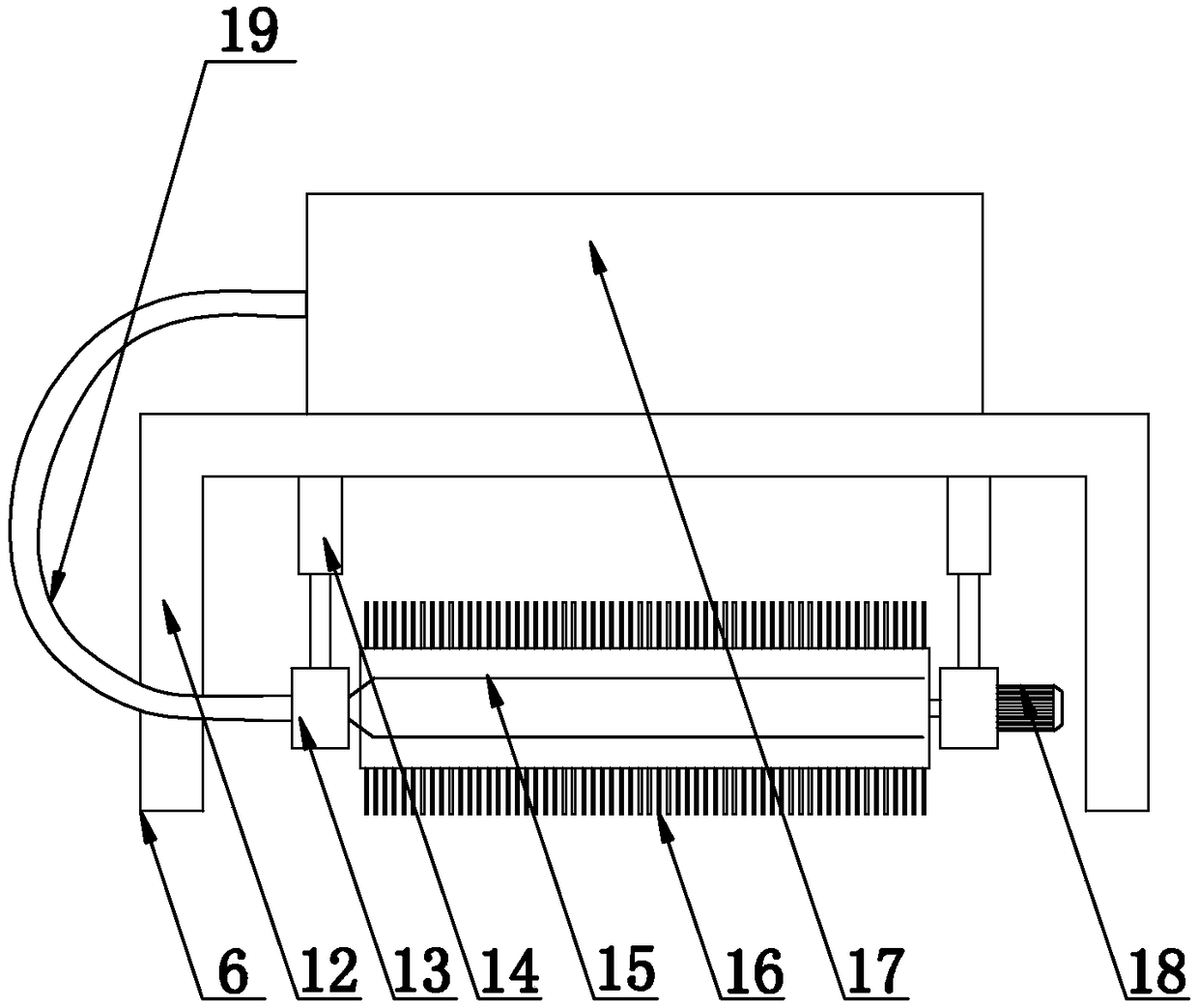
[0022] The present invention is a die-cutting machine for battery production, comprising a workbench 1, a control panel 5 is fixed on one side of the bottom of the workbench 1 by bolts, and a conveyor belt 7 is embedded in the center of the top of the workbench 1. The top side of the workbench 1 is oppositely installed with a supporting plate 2, and the inner side of one of the supporting plates 2 is rotatably connected with a deck 4, and the inner side of the other supporting plate 2 is installed with a battery pole piece through a universal rotating joint. Sleeve rod 3, the universal rotary joint is connected with the output shaft of the first rotating motor 10 installed on the outside of the support plate 2, the top center of the workbench 1 is also fixed wit...


PUM


Abstract

The invention discloses a die-cutting machine for battery production. The die-cutting machine comprises a working table, a control panel is fixed to one side of the bottom of the working table throughbolts, a conveyor belt is embedded in the center of the top of the working table, support plates are oppositely installed on one side of the top of the working table, a clamping base is rotationallyconnected to the inner side of one of the support plates, a battery pole piece sleeve rod is installed on the inner side of the other support plate through a universal rotary joint which is connectedwith an output shaft of a first rotating motor installed on the outer side of support plate, a dust removal mechanism is fixed to the center of the top of the working table through bolts, a die-cutting mechanism is fixed to the other side of the top of the working table through bolts, and the control panel is electrically connected with the dust removal mechanism, the conveyor belt and the first rotating motor. According to the die-cutting machine for battery production, the automation degree is high, and the battery pole piece product quality is high.

Description

technical field [0001] The invention relates to the technical field of die-cutting machines, in particular to a die-cutting machine for producing batteries. Background technique [0002] Due to the advantages of high energy density, high battery voltage, wide operating temperature range, long cycle life, and environmental protection, lithium-ion power batteries have been widely used in military and civilian small electrical appliances, such as mobile phones, portable computers, video cameras, cameras, etc. . With the continuous progress of science and technology, large-capacity power lithium-ion batteries have been applied in electric vehicles and become one of the main power sources of electric vehicles in the 21st century. The rapid development of the new energy vehicle industry has put forward high requirements for the safety, environmental protection and performance of high-current charging and discharging of lithium-ion batteries. In large-scale production, studies ha...

Claims


Application Information

Patent Timeline
Patent Type & Authority Applications(China)
IPC IPC(8): B26F1/44B26D7/32B26D7/18
CPCB26D7/1863B26D7/32B26F1/44
Inventor 陆海龙
Owner 江西尚立动力科技有限公司
Learn More