A sliding support device at the bottom of a curved-slant bridge support and a lateral displacement adjustment method

A support device and lateral displacement technology, applied in bridges, bridge construction, bridge parts, etc., can solve the problems of large support cracking and shear deformation, expensive replacement of large support, loss of use function, etc., to achieve anti- High compressive strength, avoiding expensive expenses and prolonging the service life

Inactive Publication Date: 2020-07-28
CHANGAN UNIV
View PDF7 Cites 0 Cited by
  • Summary
  • Abstract
  • Description
  • Claims
  • Application Information

AI Technical Summary

Problems solved by technology

On the other hand, since the upper and lower seat plates of the support are respectively connected to the bottom of the bridge and the top of the pier, excessive lateral creep will lead to large cracking and shear deformation of the support, and in severe cases, it will cause damage to the support. , loss of normal use function
[0003] Aiming at the problem of shear failure of the bearings caused by the lateral displacement of the beam body of this type of bridge, the current solution is to replace the bearings by lifting the bridge, but this process is very cumbersome and the replacement of large bearings is expensive
Obviously, there is currently no means that can simultaneously meet the necessary real-time, synchronization, convenience, and low-cost requirements.

Method used


Image

  • A sliding support device at the bottom of a curved-slant bridge support and a lateral displacement adjustment method
  • A sliding support device at the bottom of a curved-slant bridge support and a lateral displacement adjustment method
  • A sliding support device at the bottom of a curved-slant bridge support and a lateral displacement adjustment method

Examples


Embodiment Construction

[0026] The present invention will be described in further detail below in conjunction with the accompanying drawings.

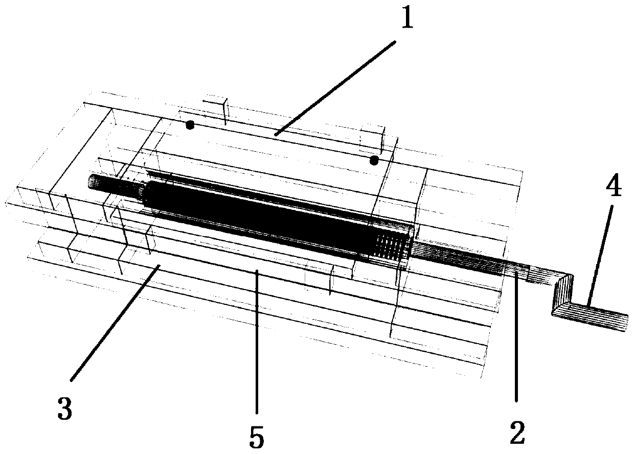
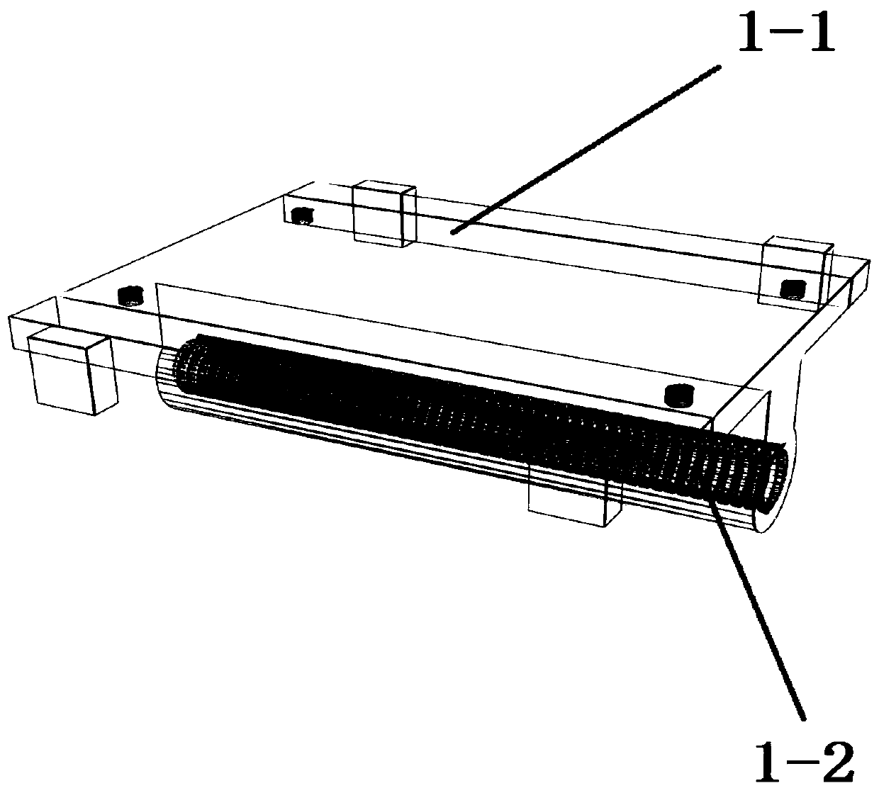
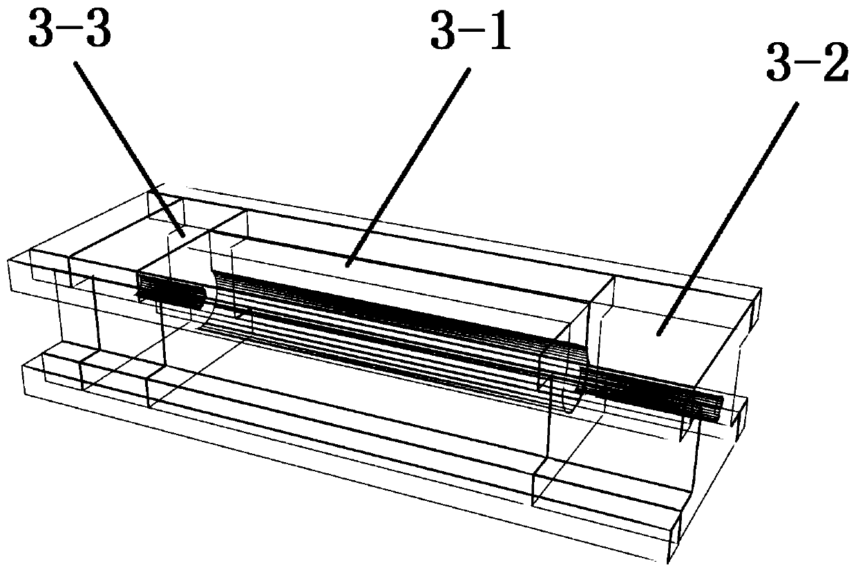
[0027] see figure 1 , The sliding support device at the bottom of the curved bridge support of the present invention structurally includes a sliding block 1, a drive screw 2, a support guide rail 3, a handle 4, a sliding gasket 5 and a temporary jack. Such as figure 2 As shown, the sliding block 1 is installed on the supporting guide rail 3, the sliding block 1 is composed of a sliding plate 1-1 and a straight thread sleeve 1-2 arranged below the sliding plate 1-1, the top of the sliding plate 1-1 is in contact with the curved The lower seat plate of the inclined bridge support is fixedly connected, the two sides of the sliding plate 1-1 are provided with limit stops 1-3 for preventing the support guide rail 3 from falling out when moving, and the transmission screw rod is installed in the straight thread sleeve 1-2 2. see Figure 4 , the driving screw 2...


PUM


Abstract

The invention provides a sliding bearing device at the bottom of a support of a curved inclined bridge and a lateral displacement adjustment method thereof. The support device comprises a sliding block mounted on a support guide rail, the sliding block is compose of a sliding plate and a straight thread sleeve, and the top of the sliding plate is fixedly connected with a lower seat plate of the support of the bent and inclined bridge; a transmission screw rod is installed in the straight thread sleeve, and the transmission screw rod is composed of an intermediate screw rod and a polished roundrod at both ends, the diameter of the intermediate screw rod is larger than the diameter of the polished round rod, a groove for placing the straight thread sleeve and the polished round rod is machined on the base, and the straight thread sleeve and the transmission screw rod are engaged together through threads. When the lateral displacement is adjusted, one jack is installed on each side of the base, starting the synchronous jacking to the set safe height, rotating several transmission screws simultaneously to realize the synchronous sliding of the sliding plates on each support guide rail, driving the bottom of the bent axle support to move horizontally along the direction of the support guide rail until the bottom of the support is returned to the designated position. The invention has the advantages of simple structure, easy operation and high precision.

Description

technical field [0001] The invention belongs to the field of road and bridge engineering, and relates to a sliding support device at the bottom of a curved and inclined bridge support and a lateral displacement adjustment method. Background technique [0002] With the improvement of highway design and construction capacity, the layout of bridges is more and more required to obey the alignment of the route. Therefore, when all or part of the bridge is located on a circular curve or a gentle curve, it is often made into a curved bridge. In the construction of modern highway engineering and urban road engineering, the number of curved bridges occupies a large proportion. The mechanical characteristics of curved bridges and inclined bridges are similar. Both of them will generate torque under the action of load, accompanied by strong bending and torsion coupling. Under the influence of various effects such as shrinkage and creep, the beam body will produce lateral displacement ...

Claims


Application Information

Patent Timeline
Patent Type & Authority Patents(China)
IPC IPC(8): E01D19/04E01D21/00
CPCE01D19/048E01D21/00
Inventor 王晓明张常权白云腾邓耀茅相源汤盛鹏舒鹏金蝶王欢
Owner CHANGAN UNIV
Why Eureka
Try Eureka