Well drilling accelerating mechanism

A technology of drilling and drilling tools, which is applied in the field of petroleum geology drilling tools, can solve the problems of no drilling pressure extension ability and the inability to improve the rock-breaking ability of the drill bit, and achieve the goals of overcoming shallow rock-breaking depth, prolonging the effective working time, and high-efficiency drilling Effect

Active Publication Date: 2019-01-25
李少江
View PDF5 Cites 4 Cited by
  • Summary
  • Abstract
  • Description
  • Claims
  • Application Information

AI Technical Summary

Problems solved by technology

[0008] The purpose of the present invention is to provide a drilling speed-increasing mechanism to alleviate the technical problems of the exis

Method used


Image

  • Well drilling accelerating mechanism
  • Well drilling accelerating mechanism
  • Well drilling accelerating mechanism

Examples


Example Embodiment

[0050] Example 1

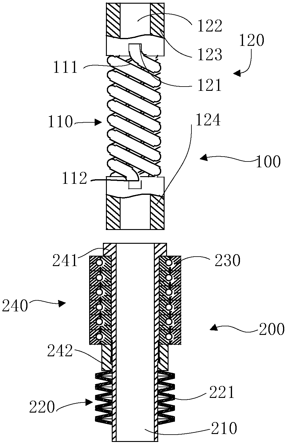
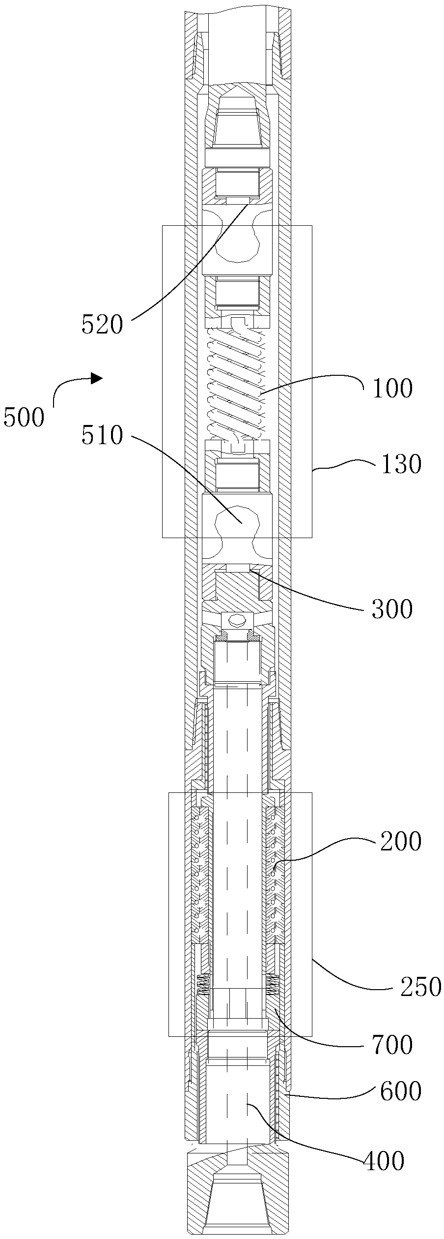
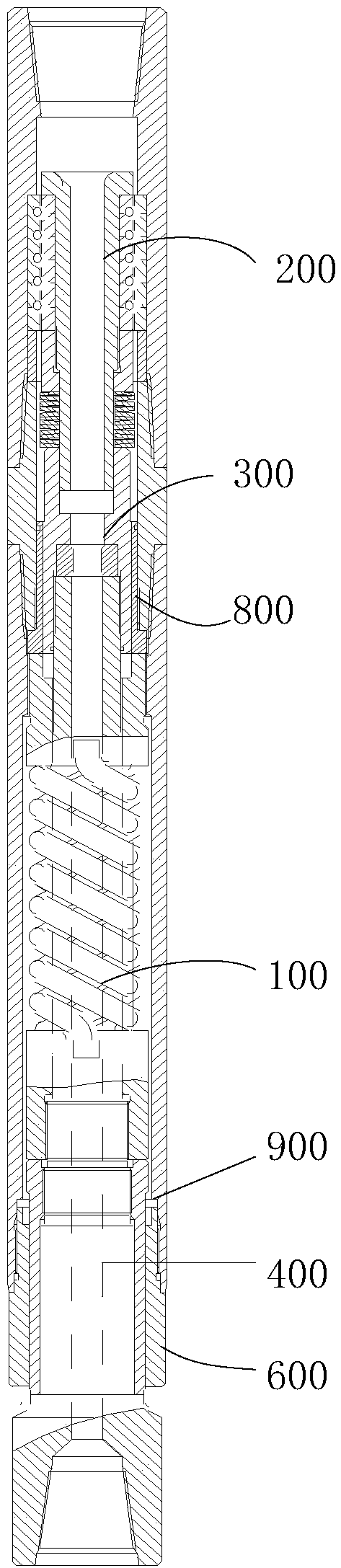
[0051] This embodiment provides a drilling speed-up mechanism, which is installed between the output shaft of the drilling tool and the power assembly. Please refer to it together Figure 1 to Figure 3 . figure 1 Is a cross-sectional view of a drilling speed-up mechanism provided by an embodiment of the present invention; figure 2 It is a schematic diagram of the installation of the drilling speed increasing mechanism in the screw drilling tool provided by the embodiment of the present invention; image 3 It is a schematic diagram of the installation of the drilling speed-up mechanism in the torsion drilling tool provided by the embodiment of the present invention.

[0052] It includes a circumferential buffer accumulator 100, an axial buffer accumulator 200 and a connecting assembly 300; the lower end of the circumferential buffer accumulator 100 is connected to the upper end of the axial buffer accumulator 200 through the connecting assembly 300; or the axial bu...

Example Embodiment

[0085] Example 2

[0086] This embodiment is another preferred solution in parallel with embodiment 1. The technical solution disclosed in embodiment 1 except for distinguishing technical features belongs to the scope disclosed in this embodiment, and embodiment 1 except for distinguishing technical features The disclosed technical solutions will not be described repeatedly.

[0087] This embodiment provides a screw drill, please refer to it together Figure 1 to Figure 2 , figure 1 Is a cross-sectional view of a drilling speed-up mechanism provided by an embodiment of the present invention; figure 2 It is a schematic diagram of the installation of the drilling speed increasing mechanism in the screw drilling tool provided by the embodiment of the present invention.

[0088] Including the drilling speed-up mechanism, the transmission shaft 400, the universal joint 500 and the transmission shaft housing 600; the axial buffer accumulator 200 is installed in the annulus between the tr...

Example Embodiment

[0095] Example 3


PUM


Abstract

The invention relates to the technical field of petroleum geology drilling tool, in particular to a well drilling accelerating mechanism. The technical problems that an existing drill bit driving drill does not have the drilling pressure extension capacity, and the drill bit rock breaking capacity cannot be improved are solved. The well drilling accelerating mechanism comprises a circumferential buffer accumulator, an axial buffer accumulator and a connecting assembly; one end of a torsional spring component is connected with a connecting component, and the other end of the torsional spring component is connected with a drilling tool output shaft or a power component; the axial buffer accumulator comprises a guide spindle and a disc spring component; the guide spindle is installed on the drilling tool output shaft or the power component; the disc spring component is installed on an outer circle of the guide spindle. Accordingly, the instantaneous rotational speed of a drill bit can beadjusted, the rock breaking efficiency of the drill bit is improved, the working life of the drill bit is prolonged, the effective action distance of drill pressure can be extended, the effective working time of the drilling tool can be prolonged, a torque fluctuation peak value of the drilling tool is reduced, the drilling speed is increased, and the drilling quality is improved.

Description

technical field [0001] The invention relates to the field of petroleum geology drilling tools, in particular to a drilling speed increasing mechanism. Background technique [0002] In petroleum geological drilling, the function of the drill bit driving tool has a great influence on the drilling speed of the drill bit. For example, the geosteering drilling system can significantly increase the drilling speed of the drill bit by increasing the effective working time of the drill bit. In hard formations, by adjusting the instantaneous speed of the drill bit, the rock-breaking depth of the PDC drill bit is improved, and the drilling speed of the drill bit is also increased. However, drill collars and power drills are the most commonly used conventional drill bit driving tools. There is no breakthrough improvement in the field, so the problem of increasing the drilling speed in conventional drilling has continued to this day. Drilling tool fatigue fracture accidents caused by lon...

Claims


Application Information

Patent Timeline
IPC IPC(8): F16F3/02F16F15/04E21B3/00
CPCE21B3/00F16F3/02F16F15/04
Inventor 李少江
Owner 李少江
Why Eureka
Try Eureka