[0015] In the following, the concept, specific structure and technical effects of the present invention will be clearly and completely described in conjunction with the embodiments and the drawings to fully understand the purpose, features and effects of the present invention. Obviously, the described embodiments are only a part of the embodiments of the present invention, rather than all the embodiments. Based on the embodiments of the present invention, other embodiments obtained by those skilled in the art without creative work belong to The scope of protection of the present invention. In addition, all the connection/connection relationships mentioned in the text do not only refer to the direct connection of the components, but refer to the fact that a better connection structure can be formed by adding or reducing connection accessories according to specific implementation conditions. The various technical features of the present invention can be combined interactively under the premise of not conflicting with each other.
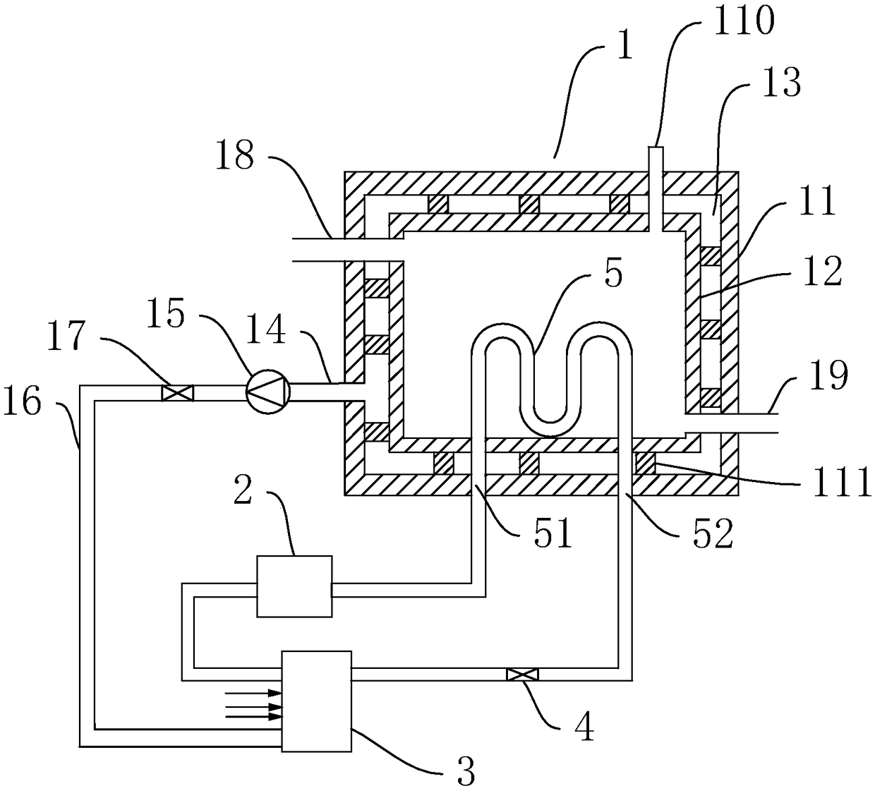
[0016] Reference figure 1 , This is an embodiment of the present invention, specifically:
[0017] An efficient heat pump insulation system, comprising a heat pump pipeline, a water supply tank 1, the water supply tank 1 is connected to the heat pump pipeline, the water supply tank 1 is a double-layer structure water tank, the water supply tank 1 includes a housing 11, The inner container 12 is arranged in the outer casing 11, a vacuum chamber 13 is formed between the outer casing 11 and the inner container 12, the outer casing 11 is connected with an evacuation tube 14, and one end of the evacuation tube 14 is in communication with the vacuum chamber 13 , The other end of the vacuum pipe 14 is connected with a vacuum pump 15, the inlet of the vacuum pump 15 is connected with the vacuum pipe 14, a vacuum sensor is installed in the vacuum chamber 13, and the vacuum sensor is electrically connected with the vacuum pump 15, so The heat pump pipeline includes a compressor 2, an air heat exchanger 3, an expansion valve 4, and a condenser 5. The condenser 5 is arranged in the inner tank 12, and the condenser 5 is connected with an inlet pipe 51 and an outlet. The inlet pipe 51 and the outlet pipe 52 respectively pass through the inner liner 12, the vacuum chamber 13, and the outer shell 11 from the inside to the outside. The outlet pipe 52 is connected to the outlet of the expansion valve 4, and the expansion valve The outlet of 4 is connected with the inlet of the air heat exchanger 3, the outlet of the air heat exchanger 3 is connected with the inlet of the compressor 2, the outlet of the compressor 2 is connected with the inlet pipe 51, and the vacuum pump 15 The outlet of is connected with an air pipe 16, the vacuum pump 15 is connected to the air heat exchanger 3 through the air pipe 16, and the heat pump pipeline is filled with heat exchange medium. The outer shell 11 and the inner tank 12 are arranged as a double-layer water tank, and the vacuum pipe 14 is set to communicate with the vacuum chamber 13, and the vacuum degree of the vacuum chamber 13 is maintained under the vacuum pump 15 to achieve the purpose of insulation and heat preservation, thereby improving the water supply tank 1. The heat pump pipeline transfers the high temperature and high pressure medium to the condenser 5 under the operation of the compressor 2 to heat the water in the inner tank 12. When the heat pump pipeline is heated to a limited temperature, the heat pump pipeline stops The vacuum pump 15 operates intermittently to keep the vacuum in the vacuum chamber 13 within a limited range, so as to ensure that the water temperature in the water supply tank 1 remains constant and reduce heat loss. At the same time, compared with the existing method of wrapping the insulation layer, The insulation of the vacuum chamber 13 can avoid the corrosion of the insulation layer, thereby increasing the service life of the equipment. In addition, the hot air drawn by the vacuum pump 15 will be delivered to the air heat exchanger 3, and then the low-temperature heat exchange medium after heat exchange will be preheated, thereby improving the heat utilization rate and reducing the energy consumption of the heat pump pipeline.
[0018] Further as a preferred embodiment, the air duct 16 is equipped with a backstop damper 17. When the vacuum pump 15 is not running, the reversible air stop door 17 prevents external air from entering the vacuum chamber 13, thereby maintaining a stable vacuum in the vacuum chamber 13 and further improving the heat preservation performance.
[0019] Further as a preferred embodiment, the upper part of the water supply tank 1 is connected with a water outlet pipe 18, the lower part of the water supply tank 1 is connected with a water inlet pipe 19, and the top of the water supply tank 1 is connected with an exhaust pipe 110, The water outlet pipe 18, the water inlet pipe 19 and the exhaust pipe 110 are all connected with the inner tank 12. The inlet pipe 19 is arranged at the lower part of the water supply tank 1 and the outlet pipe 18 is arranged at the upper part of the water supply tank 1, because the condenser 5 is arranged at the lower part of the inner tank 12, which can improve the heat exchange effect of the water and keep the inner tank 12 The water temperature is constant, and the replenishing water is heated first to increase the heating speed of the replenishing water and reduce the temperature difference of the water as much as possible.
[0020] Further as a preferred embodiment, a sealing ring is fitted between the inlet pipe 51, the inner liner 12 and the outer shell 11, and a sealing ring is fitted between the outlet pipe 52, the inner liner 12 and the outer shell 11. 18. A sealing ring is fitted between the water inlet pipe 19, the exhaust pipe 110 and the housing 11. The heat preservation performance of the water supply tank 1 is affected by the vacuum degree of the vacuum chamber 13. If the vacuum leaks, the vacuum pump 15 will run for a long time, which will increase energy consumption, which is not conducive to energy saving. The vacuum degree fluctuates too much, which will reduce the heat preservation performance.
[0021] Further as a preferred embodiment, a plurality of support blocks 111 are provided between the inner tank 12 and the outer shell 11, and the plurality of support blocks 111 are evenly arranged on the outer avoiding surface of the inner tank 12. The support blocks 111 are respectively It is fixedly connected with the outer avoiding surface of the inner liner 12 and the inner wall surface of the housing 11. The structural strength of the water supply tank 1 is improved by a plurality of support blocks 111 to prevent deformation.
[0022] As a further preferred embodiment, the supporting block 111 is made of heat insulating material. The thermal conductivity of the support block 111 is reduced, thereby further improving the heat preservation performance of the water supply tank 1.
[0023] The preferred embodiments of the present invention have been described in detail above, but the present invention is not limited to the embodiments. Those skilled in the art can make various equivalent modifications or substitutions without departing from the spirit of the present invention. These Equivalent modifications or replacements are all included in the scope defined by the claims of this application.