
A vdmos device structure with self-shutoff capability and its preparation method

A device structure and self-shutdown technology, which is applied in semiconductor/solid-state device manufacturing, semiconductor devices, electrical components, etc., can solve the problems of VDMOS devices being turned on for a long time, irreversible post-stage load, and large current, so as to improve the reliability of use, Solve the reliability risk of the gate floating, the effect of high implementation

Active Publication Date: 2021-11-16
NO 24 RES INST OF CETC
View PDF4 Cites 0 Cited by
  • Summary
  • Abstract
  • Description
  • Claims
  • Application Information

AI Technical Summary

Problems solved by technology

[0004] Among them, V TH Indicates the turn-on voltage, C OX is the characteristic capacitance of the oxide layer of the VDMOS device, μ represents the permeability coefficient, W is the width of the depletion layer of the VDMOS device, and L is the effective length of the conductive channel of the VDMOS device; The gate of the device is a floating potential, when the floating potential is very high, that is, V GS If it is too large, there will be a large current between the source and the drain, and this current will be poured into the subsequent load, which will cause irreversible damage to the latter load
[0005] When the above situation occurs, the output signal of the front-stage driver (that is, the gate input signal of the VDMOS device) will appear in a floating potential state. The phenomenon of turning on, and VDMOS is used as a power supply device in the power management module, DC-DC converter and other fields, the current passing through it is relatively large, and the VDMOS tube that is turned on for a long time will pour a large current into the subsequent load module, causing irreversible damage

Method used


Image

  • A vdmos device structure with self-shutoff capability and its preparation method
  • A vdmos device structure with self-shutoff capability and its preparation method
  • A vdmos device structure with self-shutoff capability and its preparation method

Examples


Embodiment approach

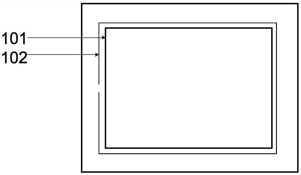
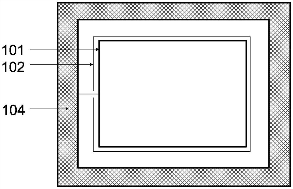
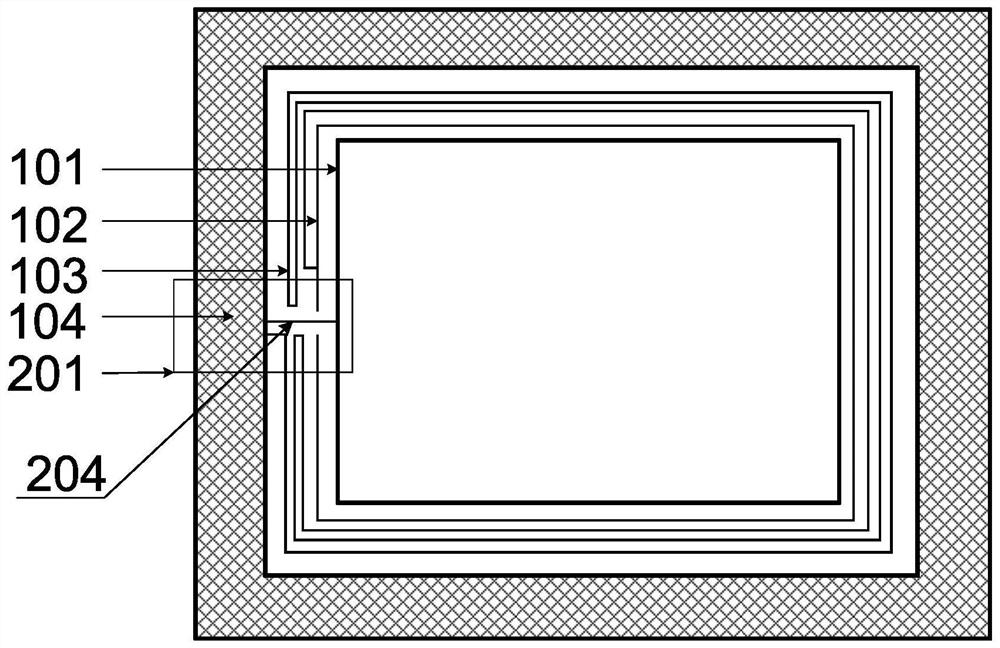
[0041]The present invention provides an embodiment. In this embodiment, if the chip cell 101 adopts a square cell of 3mm×3mm, the polysilicon resistor 103 surrounds the chip cell 101 for three weeks, and the polysilicon resistor 103 between adjacent two weeks 1um apart, this embodiment selects the block resistance R of the polysilicon resistor 103 □ =0.15Ω, wherein the width of the polysilicon resistance 103 is 0.5 μm, and the length of each cycle is about 12000 μm, then the resistance value of the polysilicon resistance 103 between the gate and the source is about 10K, and this value is used as the pull-up resistance resistance between the gate and the source The value is more reasonable; the calculation of the resistance is well known to those skilled in the art, and will not be repeated here.

[0042] In order to realize the special performance of the self-shutoff capability of the VDMOS device, the present invention provides a new terminal structure by adding a polysilicon...


PUM

PropertyMeasurementUnit
electrical resistanceaaaaaaaaaa
electrical resistivityaaaaaaaaaa

Abstract

The invention belongs to the field of discrete device design, and relates to a VDMOS device structure with self-shutoff capability and a preparation method thereof. The device structure includes a P + type substrate, the P + A P-type epitaxial layer is arranged on the P-type substrate, an N-type body region is arranged on the P-type epitaxial layer, and a P-type body region is arranged on the N-type body region. + type source region, in the formed VDMOS device structure, the peripheral metal field plate is connected with the metal part of the chip cell; the process of the present invention is simple and easy, and the implementation degree is high, and the new VDMOS structure is clear and simple, stable and reliable, and solves the problem of The reliability risk of floating gates of traditional VDMOS devices can improve the reliability of devices and has high industrial application value.

Description

technical field [0001] The invention belongs to the field of discrete device design, and relates to a VDMOS device structure with self-shutoff capability and a preparation method thereof. Background technique [0002] VDMOS devices are widely used in power management modules, DC-DC converters and other fields. In the application process, the front stage of the traditional structure VDMOS device is the driver input signal, because the front stage driver circuit and the traditional structure VDMOS device use different power supplies for power supply. , so it is very likely that the front-end driver will be powered off. In a VDMOS device, the current I between the drain and the source DS and the voltage between the gate and source V GS The relationship between them is as follows: [0003] [0004] Among them, V TH Indicates the turn-on voltage, C OX is the characteristic capacitance of the oxide layer of the VDMOS device, μ represents the permeability coefficient, W is t...

Claims


Application Information

Patent Timeline
Patent Type & Authority Patents(China)
IPC IPC(8): H01L29/78H01L29/06H01L21/336
CPCH01L29/0603H01L29/0684H01L29/66712H01L29/7802
Inventor 向凡杨丰吴昊付晓君郑直
Owner NO 24 RES INST OF CETC
Learn More