Cast iron mold with rapid demoulding function

A cast iron mold and demoulding technology, which is applied in the direction of casting molds, casting mold components, manufacturing tools, etc., can solve the problems of high labor intensity of workers and damage to cast iron molds, and achieve low labor intensity of workers, fast demoulding speed, and easy demoulding reliable effect

Pending Publication Date: 2019-01-29
荣成富邦金属科技有限公司
View PDF0 Cites 1 Cited by
  • Summary
  • Abstract
  • Description
  • Claims
  • Application Information

AI Technical Summary

Problems solved by technology

[0003] In order to overcome the shortcomings of the existing manual knocking mold demoulding, which is easy to cause damage to the cast iron mold and high labor intensity of the workers, the purpose of the present invention is to provide a fast demoulding speed, reliable demoulding, difficult mold damage, and low labor intensity. Cast iron mold with demoulding function

Method used


Image

  • Cast iron mold with rapid demoulding function
  • Cast iron mold with rapid demoulding function
  • Cast iron mold with rapid demoulding function

Examples


Embodiment 1

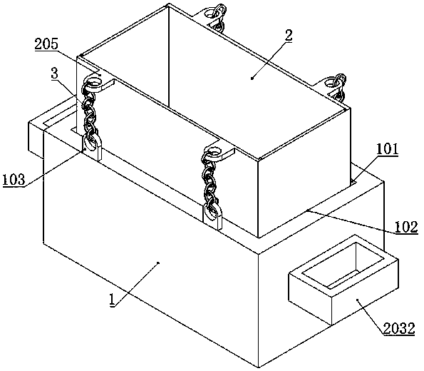
[0022] Such as figure 1 As shown, a cast iron mold with quick release function includes a base mold 1 and a casting mold 2.

[0023] Such as figure 2 As shown, the base mold 1 is a box structure, which has a mold cavity 101 and an upper open die opening 102 .

[0024] exist figure 1 Among them, the casting mold 2 is movably set in the mold cavity 101 of the base mold 1 through the die opening 102 of the base mold 1 .

[0025] In order to facilitate the casting mold 2 from the mold cavity 101 of the base mold 1, the casting mold 2 and the mold cavity 101 of the base mold 1 are fitted with a gap, and the gap difference is preferably in the range of 2 mm to 5 mm. In this embodiment, the gap difference between the mold cavity 101 of the casting mold 2 and the base mold 1 is controlled at 3.5 mm.

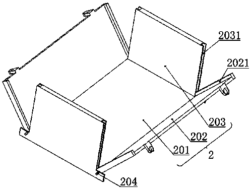
[0026] Such as image 3 As shown, the casting mold 2 includes a bottom plate 201 , two side templates 202 and two end templates 203 . Wherein, the end templates 203 are symmetrica...

Embodiment 2

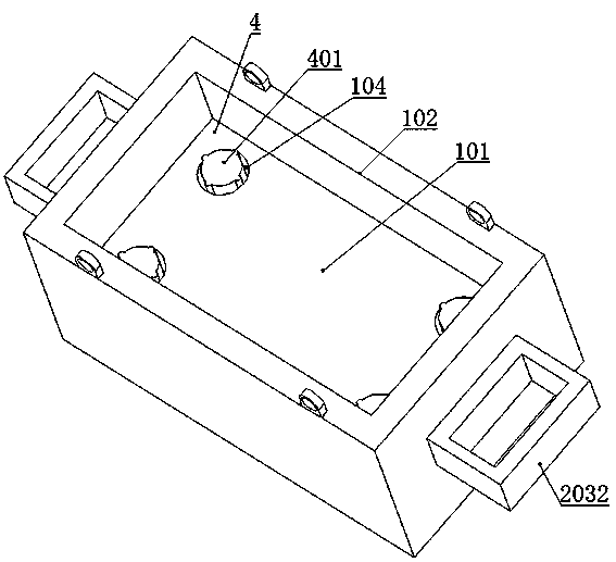
[0038] The difference from Example 1 is that, as Figure 6 As shown, the ejector device 4 includes at least one cylinder 404, and at least one accommodating chamber 106 is provided corresponding to the cylinder 404 on the bottom of the inner mold of the base mold 1, and the cylinder 404 is correspondingly fixed in the accommodating chamber 106, and the piston rod of the cylinder 404 moves against Top on the bottom plate 201 of the mold 2. The quantity of air cylinder 404 is also set according to the volume of casting mold 2, in the present embodiment, the quantity of air cylinder 404 adopts four, and then the quantity of accommodating chamber 106 is also four, and it is respectively opened in four corners of the inner mold bottom of base mold 1 superior. During application, the intake pipe of the cylinder 404 is connected to the outlet end of the power air source 7 in a conventional loop. When the casting mold 2 and the base mold 1 circulate to the ejection station at the up...


PUM


Abstract

The invention discloses a cast iron mold with a rapid demoulding function. The cast iron mold solves the problems that manual knocking demoulding is prone to causing damage of the cast iron mold and the labor intensity of workers is high. The cast iron mold comprises a base mold and a casting mold, wherein the casting mold is movably arranged in a mold cavity of the base mold through a mold opening of the base mold. The casting mold comprises a bottom plate, two side mold plates and two end mold plates, the end mold plates are symmetrically and fixedly connected to both ends of the bottom plate, and the lower ends of the side mold plates are symmetrically connected to both sides of the bottom plate by rotating shafts in a pivoted mode. Sealing grooves are formed in the end faces of the twoends of the end mold plates, sealing barrier strips are arranged on the inner side surfaces of the two ends of the side mold plates, and the barrier strips are detachably connected into the sealing grooves. Pulling cables are arranged between the upper end surfaces of the two sides of the base mold and the outer side surfaces of the upper ends of the side mold plates; and an ejector device for ejecting the casting mold is arranged at the bottom of the base mold. The pulling cables pull the side mold plates of the casting mold to be separated from the end mold plates, and iron blocks and the casting mold are directly separated without manual knocking. The demoulding speed is high, the casting mold is not prone to being damaged, and the labor intensity of the workers is low.

Description

technical field [0001] The invention relates to a permanent casting mold for molding castings, in particular to a cast iron mold with the function of quick demoulding. Background technique [0002] As we know, a cast iron machine is a device for continuously casting molten iron into iron blocks. It includes a frame that is inclined upwards. The upper and lower ends of the frame are rotatably supported by sprockets. There are many cast iron molds, the sprocket at the upper end is a transmission wheel, driven by a motor, and the sprocket at the lower end is a guide wheel. During the molten iron casting process of the cast iron machine, the molten iron in the cast iron mold runs through the chain belt, and is cooled and solidified by the cooling water to form iron blocks. When the chain belt runs to the upper end of the frame and turns over, it will automatically fall off by gravity and fall into the chute. However, in the actual operation process, the cast iron mold is affec...

Claims


Application Information

Patent Timeline
Patent Type & Authority Applications(China)
IPC IPC(8): B22C9/06B22D29/06
CPCB22C9/06B22D29/06
Inventor 董小林周志庆
Owner 荣成富邦金属科技有限公司
Why Eureka
Try Eureka