Automatic quantitative power filling equipment for novel heat tube

A powder filling and heat pipe technology, applied in the field of heat pipe production equipment, can solve the problems of low production efficiency, large dust in the working environment, waste of copper powder, etc., to improve production efficiency and automation, improve equipment automation, and improve work environmental effects

Pending Publication Date: 2019-01-29
SOUTH CHINA UNIV OF TECH +1
View PDF5 Cites 6 Cited by
  • Summary
  • Abstract
  • Description
  • Claims
  • Application Information

AI Technical Summary

Problems solved by technology

[0003] At present, the powder filling equipment mainly used in the market is divided into manual type and semi-automatic type. Among them, the manual powder filling equipment needs workers to operate the whole process, the quality of powder filling is poor, the waste of copper powder is serious, and workers are in contact with copper powder all the time, which is harmful to the body. Large, semi-automatic powder filling equipment avoids the above problems to a certain extent, and the efficiency and quality of powder filling have been improved to a certain extent
At present, manual powder filling equipment is gradually being eliminated on the market, and it is slowly developing towards precision and automation. For example, a semi-automatic powder filling equipment was announced with the application number 201820065572.1, which mainly includes a frame, a quantitative leakage mechanism, a shared filling mechanism and Mandrel centering mechanism, but this equipment has problems such as poor versatility, low production efficiency, and large dust in the working environment
The application number is 201410289104.9, which discloses a sintered heat pipe quantitative powder filling equipment, which mainly includes a left-right symmetrical V-shaped frame and a touch screen control panel set in the middle of the frame, and also includes a funnel positioning device and a left-right symmetrical set on the frame. The two sets of powder-filling core mechanisms above, although this kind of equipment reduces the labor intensity of workers to a certain extent and improves production efficiency, but there are still problems such as insufficient automation, poor versatility, low production efficiency, and harsh working environment.
[0004] In short, some existing semi-automatic powder filling equipment has similar defects, which cannot meet the increasing production needs of enterprises.

Method used


Image

  • Automatic quantitative power filling equipment for novel heat tube
  • Automatic quantitative power filling equipment for novel heat tube
  • Automatic quantitative power filling equipment for novel heat tube

Examples


Embodiment Construction

[0038] The present invention will be described in further detail below.

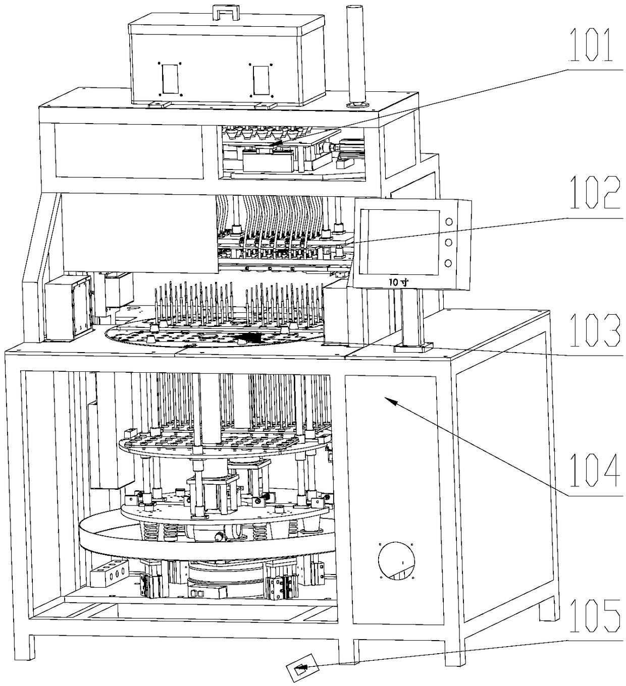
[0039] Such as figure 1 As shown, a new heat pipe automatic quantitative powder filling equipment includes a frame 104, a control device, a powder precise quantitative mechanism 101 and a lifting powder filling mechanism 102 arranged in the frame 104 in isolation from top to bottom. and the rotary table mechanism 103,

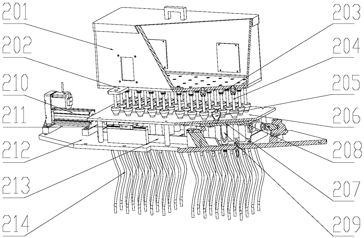
[0040] Such as figure 2 As shown, the powder precise quantification mechanism 101 is sequentially provided with a powder storage box 201, a powder storage box bottom plate 202, a fixed powder funnel 205 for powder quantification, an upper fixing plate 206, and a symmetrically distributed intermediate movement from top to bottom. plate 207, lower fixing plate 212, the powder storage box bottom plate 202 is fixed on the frame 104 for fixing the powder storage box 201, and the bottom of the powder storage box bottom plate 202 is uniformly provided with several threaded holes for fixing th...


PUM


Abstract

The invention discloses automatic quantitative power filling equipment for a novel heat tube. The automatic quantitative power filling equipment comprises a rack, a control device, a precise power quantifying mechanism, a lifting power filling mechanism and a rotating worktable mechanism; the precise power quantifying mechanism comprises a power storage box, a power storage box baseplate, hollow cylindrical tubes, power quantifying funnels, an upper fixing plate, middle movable plates, a plurality of powder storage measuring cylinders, a lower fixing plate and the like; the lifting power filling mechanism comprises a compression bar assembly fixing disk, mandrel compression bar assemblies, a copper powder tube fixing disk, replaceable powder cup assemblies, a lifting platform baseplate, alocating cylinder, a lifting cylinder and the like; the rotating worktable mechanism comprises powder filling worktables, lifting worktables, vibration baseplates, damping spring components, a power storing plate and the like; and the control device is connected to the precise power quantifying mechanism, the lifting power filling mechanism and the rotating worktable mechanism. The automatic quantitative power filling equipment has the advantages of high quality, precision, power filling efficiency, automation degree and universality, easy operation, low labor intensity and small dust.

Description

technical field [0001] The invention relates to an automatic powder filling technology, in particular to a novel heat pipe automatic quantitative powder filling equipment, which belongs to the field of heat pipe production equipment. Background technique [0002] In recent years, the rapid development and increasing demand of mobile devices, especially the widespread application of smart phones and tablet computers, has prompted the rapid development of microelectronics technology, making the integrated units of micro-control systems more and more large, while the volume is becoming larger and larger. more compact. However, the high integration of microelectronic chips and their compact packaging technology greatly reduce the effective heat dissipation space of components, resulting in a sharp increase in chip heat flux, which poses a severe test to the life and reliability of electronic products, and has become a key point for the development of microelectronic technology. ...

Claims


Application Information

Patent Timeline
Patent Type & Authority Applications(China)
IPC IPC(8): B22F3/00B22F3/03B22F5/12
CPCB22F3/004B22F3/03B22F5/106F28D15/02
Inventor 潘敏强章毅李勇梁长球陈韩荫陈创新
Owner SOUTH CHINA UNIV OF TECH
Why Eureka
Try Eureka