Optical module

An optical module and optical technology, applied in the field of optical communication, can solve the problems of large electrical signal attenuation at the welding point of flexible circuit board and PCBA, and achieve the effect of good heat dissipation effect, small assembly tolerance and excellent high-speed electrical signal transmission performance.

Active Publication Date: 2019-01-29
INNOLIGHT TECHNOLOGY (SUZHOU) LTD
View PDF7 Cites 14 Cited by
  • Summary
  • Abstract
  • Description
  • Claims
  • Application Information

AI Technical Summary

Problems solved by technology

[0004] Most of the optical module packaging technologies now use flexible circuit boards (FPC) to absorb assembly tolerances, but the welding points between flexible circuit boards and PCBA introduce large electrical signal attenuation, which can only be applied to transmission rates below 10G

Method used


Image

  • Optical module
  • Optical module
  • Optical module

Examples


Embodiment Construction

[0034] The present invention will be described in detail below in conjunction with specific embodiments shown in the accompanying drawings. However, these embodiments do not limit the present invention, and any structural, method, or functional changes made by those skilled in the art according to these embodiments are included in the protection scope of the present invention.

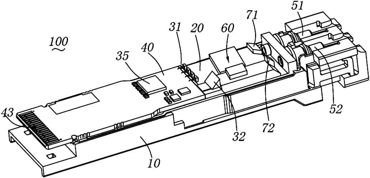
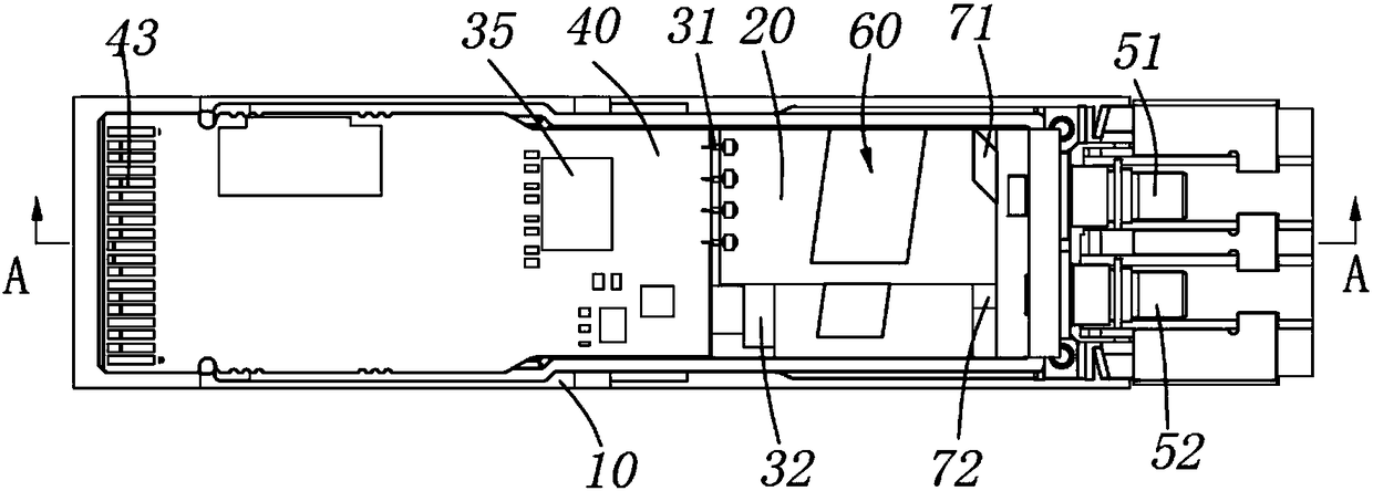
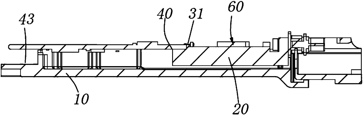
[0035] Such as Figure 1 to Figure 4 As shown, in one embodiment of the present invention, the optical module 100 includes a housing 10 (only the lower housing is shown here), a heat sink 20 disposed in the housing 10, a laser 31 disposed on the heat sink 20 and a Part of the PCB board 40 disposed on the heat sink 20 , the optical module 100 has an optical interface at one end and an electrical interface at the other end. The optical interface includes an optical interface 51 at the transmitting end and an optical interface 52 at the receiving end. The PCB board 40 is configured as a rigid board, one ...


PUM


Abstract

The invention discloses an optical module which comprises a housing, a heat sink arranged in the housing, a plurality of lasers arranged on the heat sink, a PCB which is partially arranged on the heatsink, and an optical system arranged in the housing. One end of the optical module is provided with an optical interface, and the other end is provided with an electric interface. The optical systemis arranged between the plurality of lasers and the optical interface. The optical system comprises a wavelength division multiplexer. The PCB is a hard board. The plurality of sets of laser are electrically connected with the PCB. One end of the PCB is fixed to the heat sink, and the other end is constructed to be provided with the electric interface. The optical system guides an optical wave transmitted from the laser to the optical interface. The optical module is a whole hard PCB and supplies better high-speed electric signal transmission performance.

Description

technical field [0001] The invention relates to the technical field of optical communication, in particular to an optical module. Background technique [0002] With the development of society, the amount of data is increasing. The requirements for faster transmission rate and lower cost are put forward for the optical communication module. Existing 3G can no longer meet the complex needs of users and markets, and TD-LTE (Time Division-LongTerm Evolution, the long-term evolution of TD-SCDMA) emerged as a technology from 3G to 4G. Due to the current shortage of optical fiber resources, the high cost of new laying, and the long distance distribution of base stations, the demand for optical modules in small form-factor pluggable (SFP+) packages is gradually increasing. [0003] Usually, in the optical module structure, the electrical signal enters the PCBA from the golden finger, and then outputs to the optoelectronic chip, which converts the electrical signal into an optical ...

Claims


Application Information

Patent Timeline
Patent Type & Authority Applications(China)
IPC IPC(8): G02B6/42
CPCG02B6/4272G02B6/428G02B6/4287G02B6/4296
Inventor 孙雨舟陈龙于登群李伟龙
Owner INNOLIGHT TECHNOLOGY (SUZHOU) LTD
Why Eureka
Try Eureka