A dust removal device and high-temperature waste gas treatment equipment
A dust removal device and airflow technology, applied in transportation and packaging, chemical instruments and methods, separation methods, etc., can solve the problem of not considering the balanced use of ceramic filter tubes to filter resources, etc.
- Summary
- Abstract
- Description
- Claims
- Application Information
AI Technical Summary
Problems solved by technology
Method used
Image
Examples
Embodiment 1
[0048] This embodiment discloses a dust removal device. In the case of no conflict or contradiction, the whole and / or part of the content of the preferred implementations of other embodiments can be used as a supplement to this embodiment.
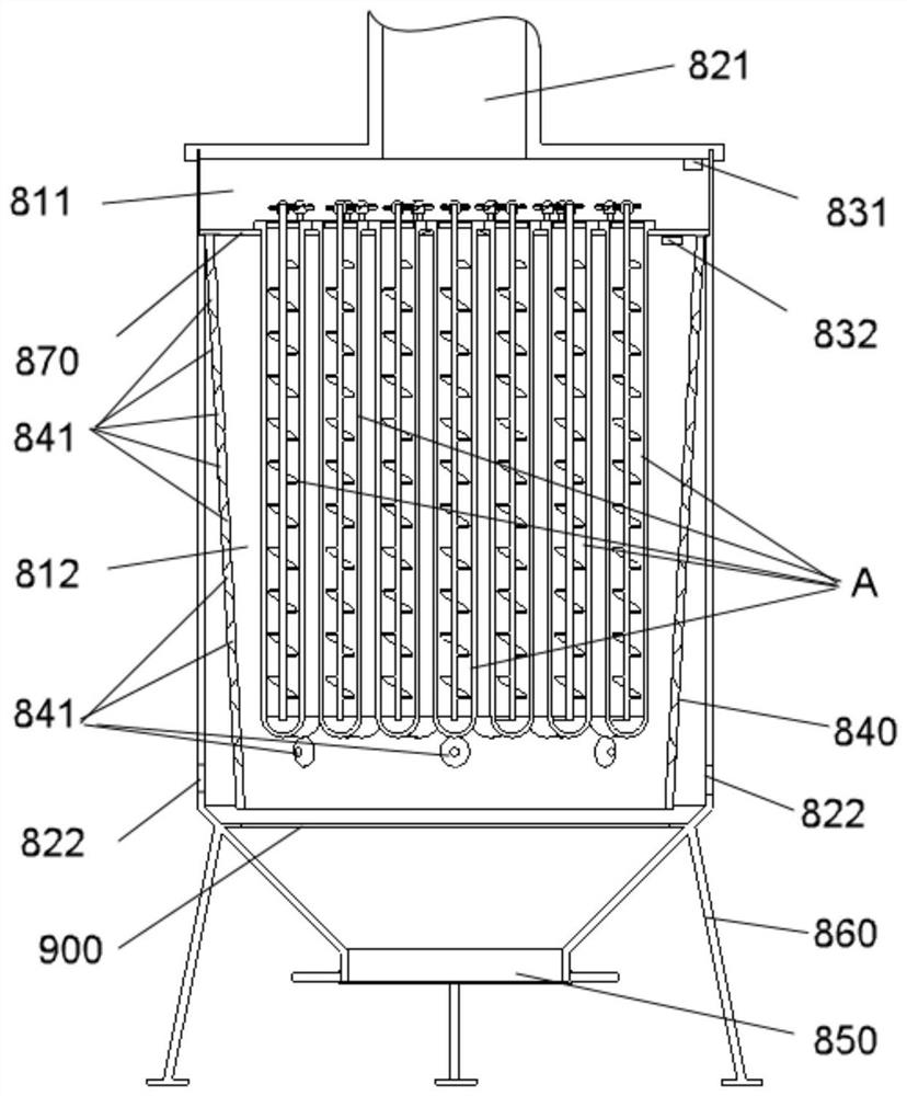
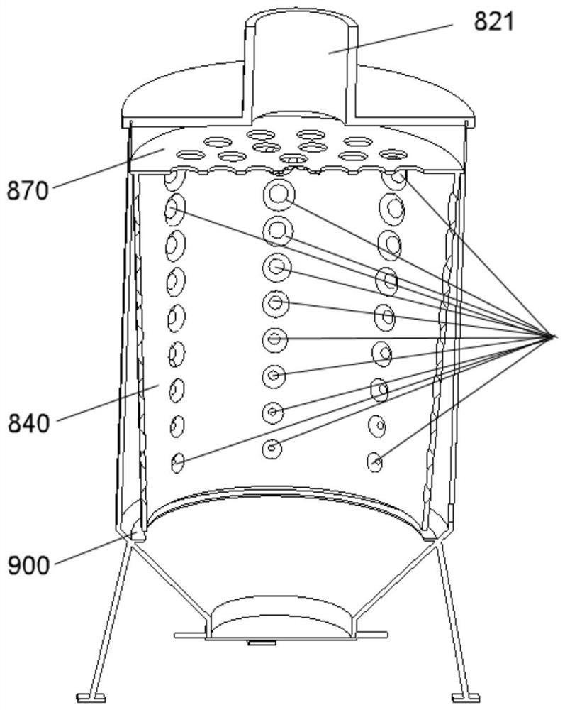
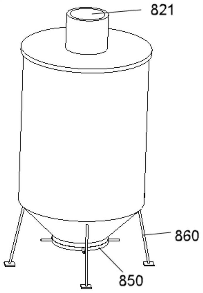
[0049] According to a preferred embodiment, a dust removal device, see figure 1 , 2 and 3 may include a hollow shell and a partition 870 disposed inside the shell. The partition 870 at least separates the first chamber 811 and the second chamber 812 formed by the casing. A plurality of ceramic filter pipes A may be vertically arranged side by side on the partition 870 . The dedusting device can be configured as gas flowing from the first chamber 811 to the second chamber 812 or from the second chamber 812 to the first chamber 811 must be filtered by the ceramic filter structure. The ceramic filter structure may include a ceramic filter tube A, and the ceramic filter tube A may include a tube body 100 of ceramic fibers for filtering. Th...
Embodiment 2
[0057] This embodiment can be a further improvement on Embodiment 1. In the case of no conflict or contradiction, the whole and / or part of the content of preferred implementations of other embodiments can be used as a supplement to this embodiment.
[0058] According to a preferred embodiment, a dust removal device may include a hollow shell and a partition 870 disposed inside the shell. The housing may be divided into a first chamber 811 and a second chamber 812 by a partition 870 . Several ceramic filter tubes A may be provided on the partition 870 . The dedusting device may be configured such that the gas must pass through the wall of the ceramic filter tube A when flowing from the first chamber 811 to the second chamber 812 or from the second chamber 812 to the first chamber 811 . The ceramic filter tube A may include a tube body 100 of ceramic fibers for filtering. Two-way air communication is realized between the inside of the tube body 100 and the outside of the tube ...
Embodiment 3
[0064] This embodiment can be further improved on the points of Embodiment 1 and / or 2. This embodiment discloses a high-temperature exhaust gas treatment equipment, which adopts the dust removal device E of the present invention. In the case of no conflict or contradiction, the whole and / or part of the content of the preferred implementations of other embodiments may serve as supplements to this embodiment.
[0065] According to a preferred embodiment, a high-temperature exhaust gas treatment equipment includes a deacidification device C and a denitrification device D, and the high-temperature exhaust gas treatment equipment also includes a dust removal device E in one of the aforementioned modes; wherein, the dust removal device E is in air communication with the combustion chamber B, And before the exhaust gas reaches the dust removal device E, the filtered air flow formed by the flow of the waste gas passes through the deacidification treatment of the deacidification device ...
PUM
 Abstract
Description
Claims
Application Information
 - R&D
- Intellectual Property
- Life Sciences
- Materials
- Tech Scout
- Unparalleled Data Quality
- Higher Quality Content
- 60% Fewer Hallucinations
Browse by: Latest US Patents, China's latest patents, Technical Efficacy Thesaurus, Application Domain, Technology Topic, Popular Technical Reports.
© 2025 PatSnap. All rights reserved.Legal|Privacy policy|Modern Slavery Act Transparency Statement|Sitemap|About US| Contact US: help@patsnap.com


