Catalyst anti-wear method for selective catalytic reduction denitration device

A catalyst and selective technology, applied in the fields of chemical instruments and methods, separation methods, gas treatment, etc., can solve the problems of flow field performance diagnosis and optimization inaccuracy, catalyst wear of reduction and denitrification devices, etc.

Inactive Publication Date: 2019-02-01
DATANG DONGBEI ELECTRIC POWER TESTING & RES INST +1
View PDF8 Cites 2 Cited by
  • Summary
  • Abstract
  • Description
  • Claims
  • Application Information

AI Technical Summary

Problems solved by technology

[0004] The purpose of the present invention is to provide a catalyst anti-wear method for selective catalytic reduction and denitrification devices to solve the problems of partial wear of catalysts in existing selective catalytic reduction and denitrification devices, inaccurate flow field performance diagnosis and optimization, etc.

Method used


Image

  • Catalyst anti-wear method for selective catalytic reduction denitration device
  • Catalyst anti-wear method for selective catalytic reduction denitration device

Examples


Embodiment Construction

[0025] The specific implementation manners of the present invention will be further described in detail below in conjunction with the accompanying drawings and embodiments. The following examples are used to illustrate the present invention, but are not intended to limit the scope of the present invention.

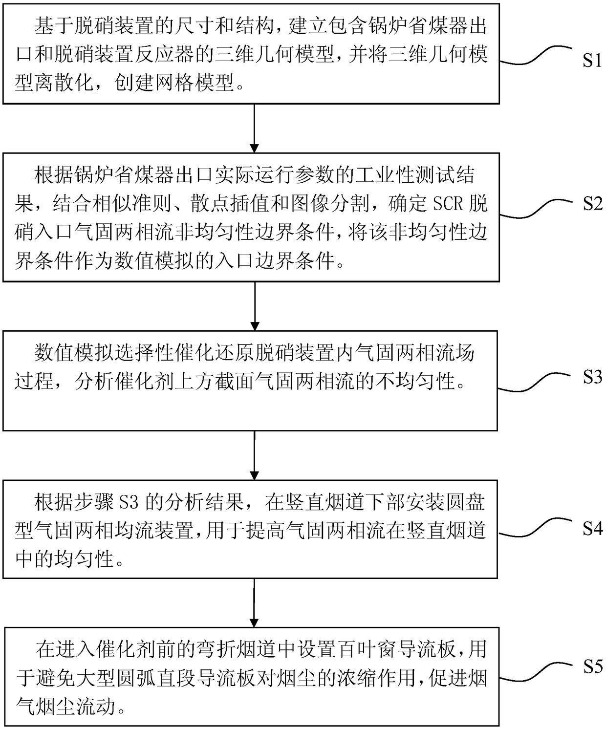
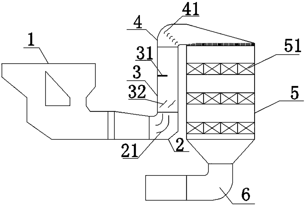
[0026] ginseng figure 1 and figure 2 As shown, this embodiment provides a catalyst wear prevention method for a selective catalytic reduction denitrification device, which includes the following steps:

[0027] Step S1, based on the size and structure of the denitrification device, establish a three-dimensional geometric model including the outlet 1 of the boiler economizer and the reactor of the denitrification device, and discretize the three-dimensional geometric model to create a grid model;

[0028] Step S2, according to the industrial test results of the actual operating parameters of boiler economizer outlet 1, combined with the similarity criterion, scatter inte...


PUM


Abstract

The invention relates to a catalyst anti-wear method for a selective catalytic reduction denitration device. The invention comprises the following steps: based on the size and the structure of the denitration device, establishing a three-dimensional geometric model including a boiler coal economizer outlet and a denitration device reactor, and discretizing the three-dimensional geometric model tocreate a mesh model; determining the non-uniformity boundary condition of the gas-solid two-phase flow at a SCR denitration inlet, and using the non-uniformity boundary condition as an inlet boundarycondition for numerical simulation; performing numerical simulation on a gas-solid two-phase flow field process in the selective catalytic reduction denitration device, and performing analysis on theheterogeneity of the gas-solid two-phase flow above the catalyst; a disc-type gas-solid two-phase flow equalizing device is installed in the lower part of a vertical flue; and a louver baffle is arranged in a bent flue before entering the catalyst. The method solves the problem that the simulation precision of the flue gas field of the selective catalytic reduction denitration device is low, the flow field performance diagnosis and the optimization misalignment, the denitration efficiency of the denitration device is improved, and the ammonia escape rate of the denitration device is reduced.

Description

technical field [0001] The invention belongs to the technical field of air pollution control of coal-fired boilers, and in particular relates to a catalyst wear prevention method for a selective catalytic reduction denitrification device. Background technique [0002] Selective catalytic reduction denitrification technology is currently the most effective and widely used technology for removing nitrogen oxides in flue gas. Using numerical simulation to simulate the actual flue gas flow process of the selective catalytic reduction denitrification device has become an important means and content of the design and transformation of the denitrification device. [0003] Limited by the spatial arrangement of boilers and SCR denitrification reactors, the asymmetric gradual expansion of the flue, the turning, and the sudden change in the section of the turning are widely used in the SCR denitrification system of coal-fired units, resulting in the boiler economizer outlet to the firs...

Claims


Application Information

Patent Timeline
Patent Type & Authority Applications(China)
IPC IPC(8): B01D53/88B01D53/56
CPCB01D53/56B01D53/885B01D2258/0283
Inventor 雷鉴琦吴春华陈城孙英浩吕秀川闫俊刚严冰清张德强周洋
Owner DATANG DONGBEI ELECTRIC POWER TESTING & RES INST
Why Eureka
Try Eureka