Video-assisted glue dispensing method for LC optical fiber connector

A fiber optic connector and glue dispensing technology, which is applied to the surface coating liquid device, coating, etc., can solve the problems such as the concentricity and deviation of the tail handle contour circle

Inactive Publication Date: 2019-02-01
苏州席正通信科技有限公司
View PDF8 Cites 3 Cited by
  • Summary
  • Abstract
  • Description
  • Claims
  • Application Information

AI Technical Summary

Problems solved by technology

[0006] At present, due to the plastic structure of the LC-type optical connector boot, there is a certain natural curvature, so the tail contour circle of the dispe...

Method used


Image

  • Video-assisted glue dispensing method for LC optical fiber connector
  • Video-assisted glue dispensing method for LC optical fiber connector
  • Video-assisted glue dispensing method for LC optical fiber connector

Examples


Embodiment

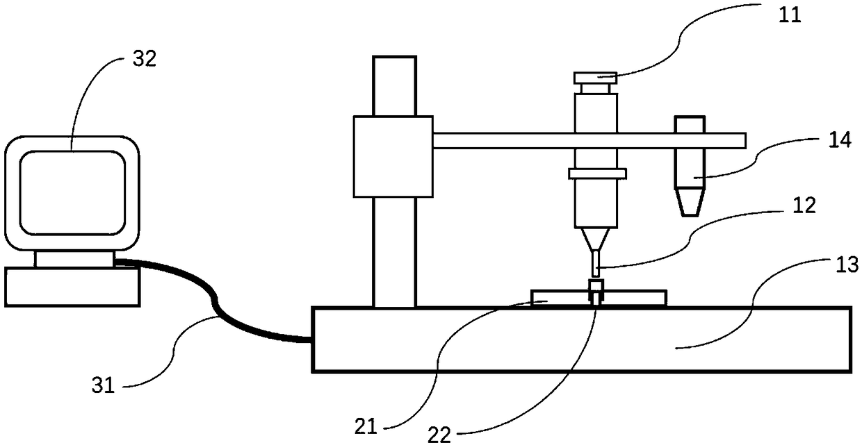
[0046] Such as figure 1 As shown, a dispensing machine is provided, including: a dispensing cylinder 11, a camera 14, a connector fixing fixture 21, a dispensing machine base 13, a control computer 32, and a communication cable 31;

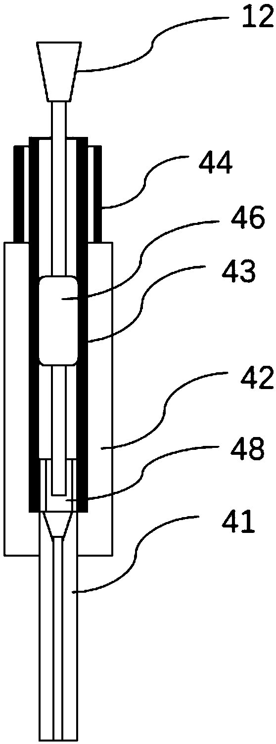
[0047] Further, a flexible dispensing needle 12 is provided, and the flexible needle is installed on the dispensing cylinder 11;

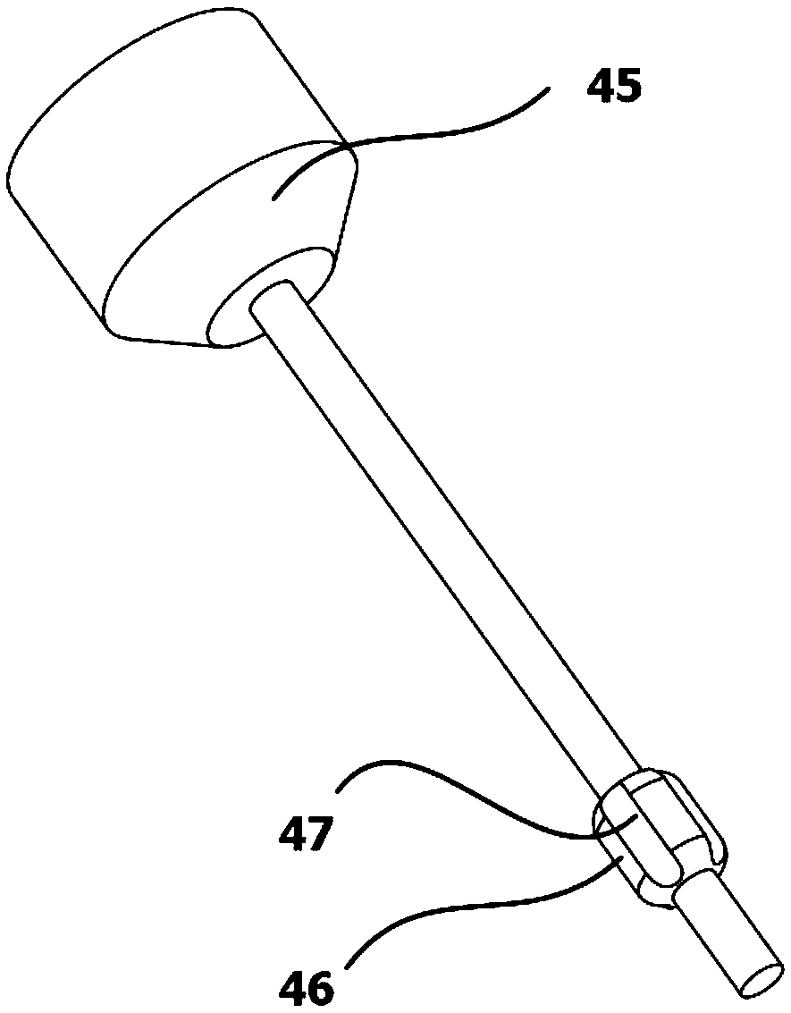
[0048] Further, such as image 3 As shown, a guide 46 is installed on the flexible needle 12;

[0049] Further, an LC type optical fiber connector 22 is provided;

[0050] Further, the LC type optical fiber connector 22 is installed on the dispensing base 13 through the connector fixing fixture 21;

[0051] Further, the tail of the LC-type optical fiber connector is photographed by the camera 14;

[0052] Further, such as Figure 4 As shown, the captured images include: metal support tube tail image 51 and tail sleeve image 53;

[0053] Further, such as Figure 5 As shown, the metal support tube tail image 51 an...


PUM


Abstract

The invention discloses a video-assisted glue dispensing method for an LC optical fiber connector. The video-assisted glue dispensing method comprises the following steps: a glue dispenser, comprisinga glue dispensing tube, a camera, a connector fixing clamp, a glue dispenser base, a control computer and a communication cable, is provided; a flexible needle on which a guider is mounted is provided, and the flexible needle is mounted on the glue dispensing tube; the LC optical fiber connector is provided and mounted on the glue dispensing base; the tail part of the LC optical fiber connector is shot by the camera, and shot images comprise an image of the tail part of a metal support tube and an image of a tail sleeve; the image of the tail part of the metal support tube and the image of the tail sleeve are analyzed by an image processing program to seek out the center of the metal support tube and the center of the tail sleeve; a point, close to the center of the metal support tube, ona connecting line of the center of the metal support tube and the center of the tail sleeve is determined as a glue dispensing location; the glue dispensing tube on the glue dispenser is controlled and the flexible needle is driven to be aligned with the glue dispensing location through the control system; the control system drives the glue dispensing tube and enables the flexible needle to stretch into the tail sleeve of the LC optical fiber connector; the flexible needle reaches a mortice tail handle and then stops moving; and the control system drives a piston to move and pushes glue to beinjected into the tail handle. The tail part of the LC optical fiber connector is shot by video recognition, the center of the tail sleeve and the center of the metal support tube are analyzed by theimage processing program, and the glue dispensing location is determined. Since the glue dispensing location is within a region of not only the tail sleeve but also the mortice tail handle, the flexible needle can be successfully inserted into the mortice tail handle.

Description

technical field [0001] The invention relates to the optical fiber communication industry, in particular to a dispensing method for video-assisted LC optical fiber connectors. Background technique [0002] Optical fiber communication is a communication method that modulates signals such as images and data to be transmitted onto an optical carrier, and uses optical fiber as a transmission medium. The frequency of light waves as a carrier is much higher than that of radio waves, and the loss of optical fibers as a transmission medium is much lower than that of coaxial cables or waveguides. Therefore, compared with cable communication or microwave communication, optical fiber communication has many unique advantages. [0003] Optical fiber connector is a device for detachable connection between optical fiber and optical fiber. It precisely butts the two end faces of optical fiber so that the optical energy output by the transmitting optical fiber can be coupled to the receiving ...

Claims


Application Information

Patent Timeline
IPC IPC(8): B05C5/02
CPCB05C5/0212
Inventor 谷丽芳
Owner 苏州席正通信科技有限公司
Why Eureka
Try Eureka