Dispensing method for LC-type optical fiber connector

A fiber optic connector and optical connector technology, which is applied in the coupling of optical waveguide, light guide, optics, etc., can solve the problems of deviation, inability to concentric the tail handle contour circle, etc., and achieve the effect of smooth entry and exit

Inactive Publication Date: 2019-02-01
苏州席正通信科技有限公司
View PDF4 Cites 2 Cited by
  • Summary
  • Abstract
  • Description
  • Claims
  • Application Information

AI Technical Summary

Problems solved by technology

[0006] At present, due to the plastic structure of the LC-type optical connector boot, there is a certain natural curvature, so the tail contour circle of the dispensing needle inserted into the boot can not be concentric with the tail handle contour circle, and there are a large number of product branches. There is a big deviation

Method used


Image

  • Dispensing method for LC-type optical fiber connector
  • Dispensing method for LC-type optical fiber connector
  • Dispensing method for LC-type optical fiber connector

Examples


Embodiment

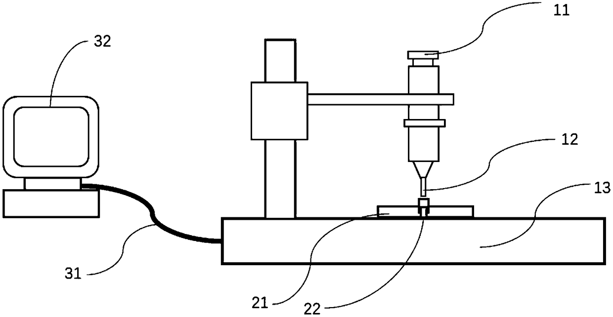
[0040] Such as figure 1 As shown, a dispensing machine is provided, including: a dispensing cylinder 11, a connector fixing fixture 21, a dispensing machine base 13, a control computer 32, and a communication cable 31;

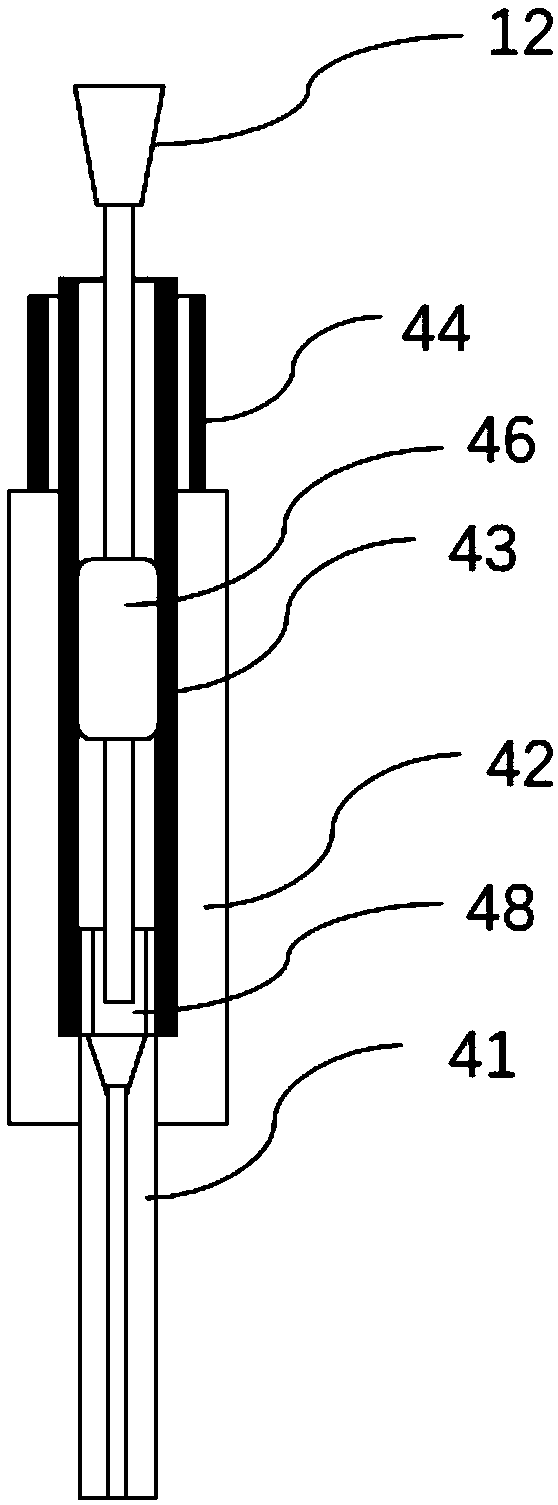
[0041] Further, a flexible dispensing needle 12 is provided, and the flexible needle is installed on the dispensing cylinder 11;

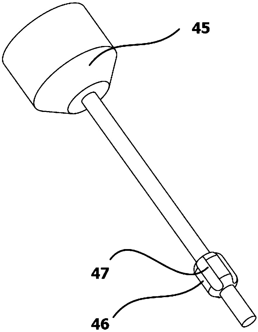
[0042] Further, such as image 3 As shown, a guide 46 is installed on the flexible needle 12;

[0043] Further, an LC type optical fiber connector 22 is provided;

[0044] Further, the LC type optical fiber connector 22 is installed on the dispensing base 13 through the connector fixing fixture 21;

[0045] Further, the position of the tail sleeve 43 on the LC-type optical connector 22 is determined by mechanically adjusting the positioning or optical positioning and shooting in advance;

[0046] Further, the glue dispenser is controlled by a control system preinstalled in the control computer 32 .

[0047] Further, control th...


PUM


Abstract

The invention discloses a dispensing method for an LC-type optical fiber connector, and provides a dispenser, a flexible needle, and a LC-type optical fiber connector. The dispenser comprises a dispensing cylinder, a connector fixing clamp, a dispenser base, a control computer, and a communication cable. A guide is mounted on the flexible needle. The flexible needle is mounted on the dispensing cylinder. The LC-type optical fiber connector is mounted on the dispenser base. The position of a tail bushing of the LC-type optical fiber connector is determined by pre-mechanical adjustment and positioning or optical positioning and shooting. The distance between the dispensing cylinder of the dispenser and the tail bushing of the LC-type optical fiber connector is controlled by a control system.The control system drives the dispensing cylinder and pushes the flexible needle into the tail bushing of the LC-type optical fiber connector. The flexible needle stops when it reaches a tail handleof a ferrule. The control system drives a piston to move and injects glues into the tail handle. The dispensing cylinder is lifted up while glues are injected. The flexible needle of the invention canbe freely bent and can conform to the bending of the tail bushing when the flexible needle enters the tail bushing. The outer wall of the guide is closely attached to the inner wall of the tail bushing. Since the guide is coaxial with the needle, the needle can be coaxial with the inner wall of the tail bushing to ensure that the flexible needle smoothly enters the tail handle of the ferrule.

Description

technical field [0001] The invention relates to the optical fiber communication industry, in particular to a glue dispensing method for an LC type optical fiber connector. Background technique [0002] Optical fiber communication is a communication method that modulates signals such as images and data to be transmitted onto an optical carrier, and uses optical fiber as a transmission medium. The frequency of light waves as a carrier is much higher than that of radio waves, and the loss of optical fibers as a transmission medium is much lower than that of coaxial cables or waveguides. Therefore, compared with cable communication or microwave communication, optical fiber communication has many unique advantages. [0003] Optical fiber connector is a device for detachable connection between optical fiber and optical fiber. It precisely butts the two end faces of optical fiber so that the optical energy output by the transmitting optical fiber can be coupled to the receiving opt...

Claims


Application Information

Patent Timeline
Patent Type & Authority Applications(China)
IPC IPC(8): G02B6/38
CPCG02B6/3889
Inventor 谷丽芳
Owner 苏州席正通信科技有限公司
Why Eureka
Try Eureka