Eureka AIR delivers breakthrough ideas for toughest innovation challenges, trusted by R&D personnel around the world.

Encapsulation pulse power capacitor

A pulsed power, capacitor technology, applied in capacitors, fixed capacitors, multiple fixed capacitors, etc., can solve the problems of low reliability and safety, expansion breakdown high-voltage arcing, complicated welding process, etc., to improve product acceleration capability , improve reliability and improve production efficiency

Pending Publication Date: 2019-02-01
FUJIAN TORCH ELECTRON TECH CO LTD
View PDF0 Cites 2 Cited by
  • Summary
  • Abstract
  • Description
  • Claims
  • Application Information

AI Technical Summary

Problems solved by technology

However, for pulse power capacitors with this structure, due to the expansion of the capacitor when it is heated and the ambient temperature changes, it is easy to squeeze each other due to expansion between the capacitor and the capacitor or between the capacitor and the metal electrode sheet, resulting in the expansion stress of the capacitor. Cracks are generated due to damage, and there is a risk of expansion breakdown and high-voltage flashover, and the reliability and safety are low
On the other hand, the existing capacitors are directly fixed on the metal electrode sheets by welding, the welding process is complicated, time-consuming and low in work efficiency

Method used


Image

  • Encapsulation pulse power capacitor
  • Encapsulation pulse power capacitor
  • Encapsulation pulse power capacitor

Examples


Embodiment Construction

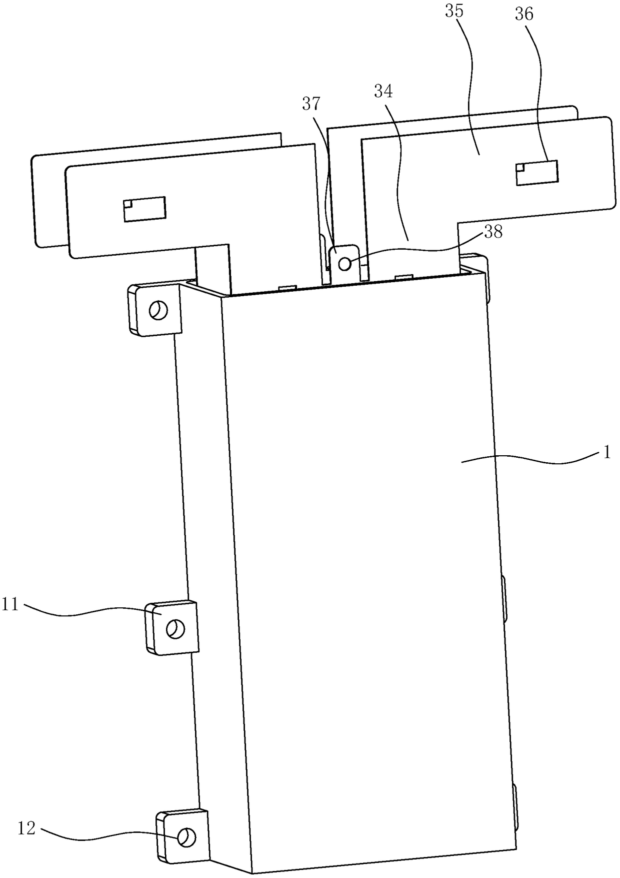
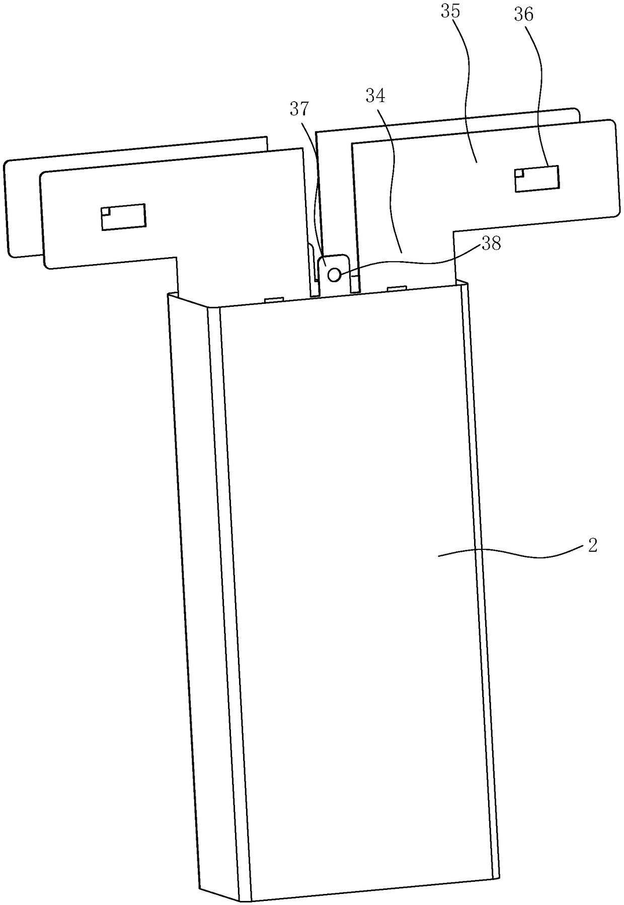
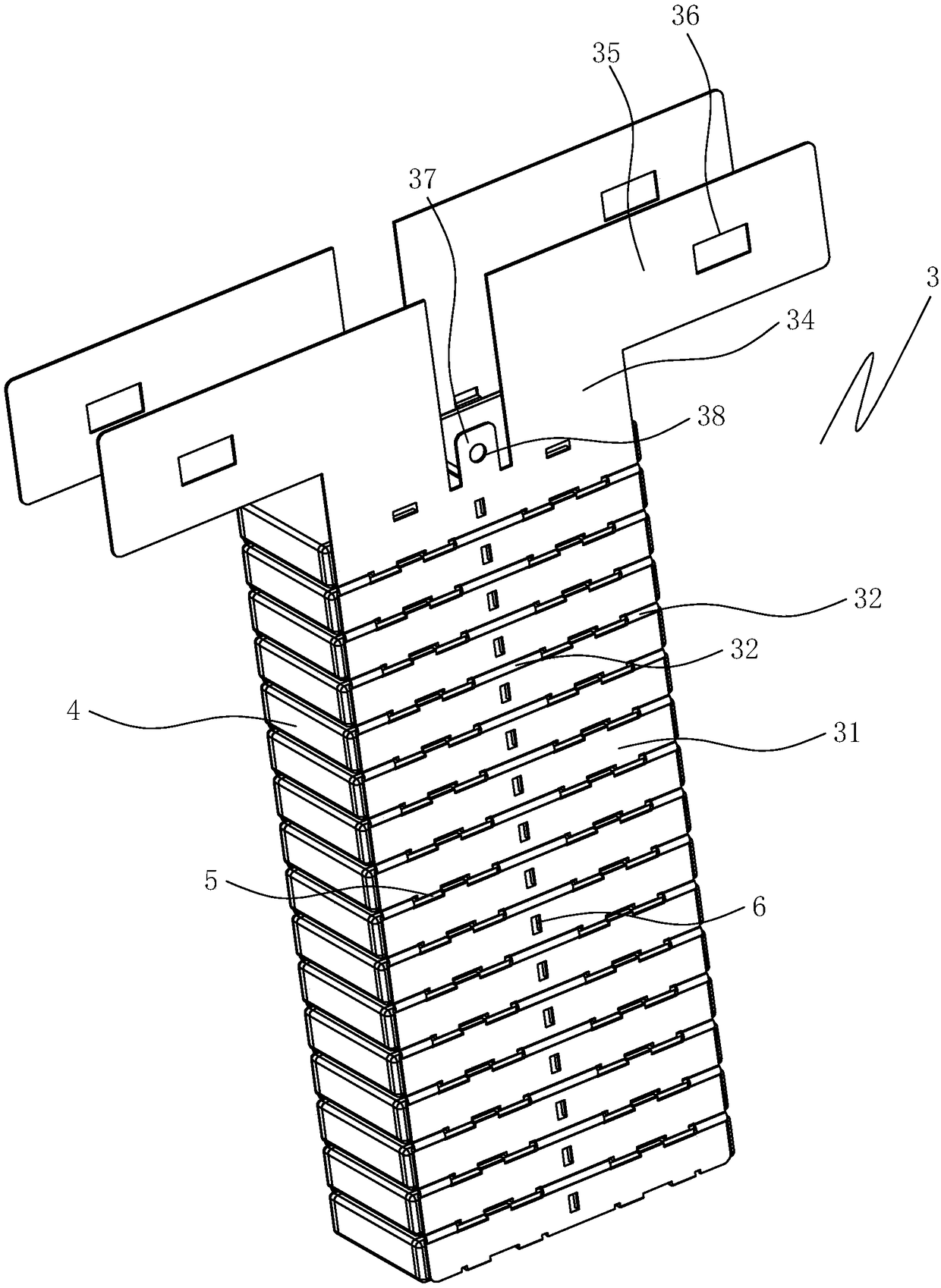
[0026] Such as Figure 1 to Figure 5 As shown, the potting pulse power capacitor includes a plastic casing 1, a potting adhesive layer 2, two metal electrode sheets 3 and several capacitors 4, and three mounting plates 11 are arranged on both sides of the plastic casing 1 at intervals, and a mounting plate 11 is provided on the mounting plate 11. The hole 12, the capacitor 4 is a pulse power capacitor 4, and several capacitors 4 are connected in parallel through two metal electrode sheets 3, and the metal electrode sheet 3 includes several electrode plates 31 arranged vertically at intervals, and expansion joints 32 are arranged between adjacent two electrode plates 31 , the electrode plate 31 is provided with two clamping mechanisms 5 at intervals, the number of the clamping mechanisms 5 is the same as the number of capacitors 4, the two metal electrode pieces 3 are arranged in the plastic casing 1 at intervals, and the clamping mechanisms 5 of the two metal electrode pieces 3...


PUM


Abstract

The present invention provides an encapsulation pulse power capacitor. The encapsulation pulse power capacitor comprises a plastic package housing, an encapsulation glue layer, two metal electrode slices and a plurality of capacitors. The capacitors are connected in parallel through the two metal electrode slices, each two metal electrode slice comprises a plurality of electrode plates, one expansion joint is arranged between each two adjacent electronic plates, the electrode plates are provided with clamping plate mechanisms, the two metal electrode slices are arranged at intervals in the plastic package housing, the clamping plate mechanisms of the two metal electrode slices are oppositely arranged to form necks fixing the capacitors, the capacitors are stacked between the two metal electrode slices, capacitors are clamped in the corresponding necks, two ends of the capacitors are welded on the corresponding electrode plates, and the encapsulation glue layer is arranged between the plastic package housing and the capacitors and between the adjacent capacitors. The necks are employed to fix the capacitors and weld the capacitors to allow the welding to be convenient and rapid, effectively buffer the extension stress of the capacitors, avoid crack of the capacitors and avoids phenomena of generation of expansion breakdown and flashover.

Description

technical field [0001] The invention relates to a potting pulse power capacitor. Background technique [0002] In existing pulse power capacitors, in order to increase capacitor capacitance and energy storage energy, multiple capacitors are usually connected in parallel as energy storage units, and multiple capacitors are connected in parallel through metal electrode sheets connected to capacitor electrodes. However, for pulse power capacitors with this structure, due to the expansion of the capacitor when it is heated and the ambient temperature changes, it is easy to squeeze each other due to expansion between the capacitor and the capacitor or between the capacitor and the metal electrode sheet, resulting in the expansion stress of the capacitor. Cracks are generated due to damage, and there is a risk of expansion breakdown and high-voltage flashover, and the reliability and safety are low. On the other hand, the existing capacitors are directly fixed on the metal electr...

Claims


Application Information

Patent Timeline
Patent Type & Authority Applications(China)
IPC IPC(8): H01G4/38H01G4/236H01G4/224H01G2/06
CPCH01G2/06H01G4/224H01G4/236H01G4/385
Inventor 郑惠茹朱江滨吴文辉蔡约轩王凯星
Owner FUJIAN TORCH ELECTRON TECH CO LTD
Why Eureka
Eureka Blog
Learn More