
Broadband high-gain Vivaldi antenna
A high-gain, antenna technology, applied in the field of antennas, can solve problems such as poor performance, achieve stable radiation characteristics, simple structure, and correct the deviation of the electric field direction
- Summary
- Abstract
- Description
- Claims
- Application Information
AI Technical Summary
Problems solved by technology
Method used
Image

Examples
Embodiment Construction
[0017] The present invention will be further described below in conjunction with the accompanying drawings and specific embodiments.
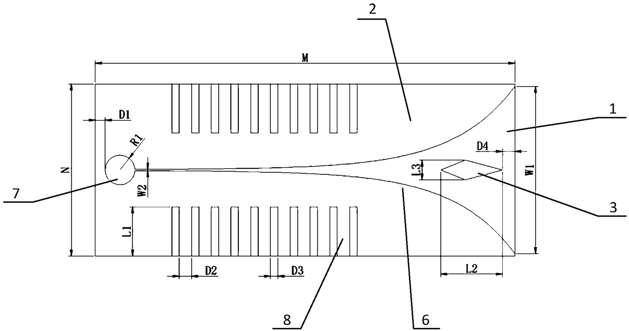
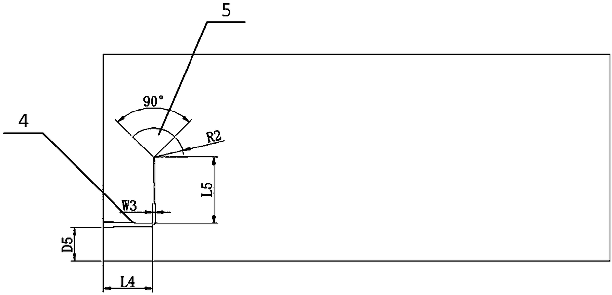
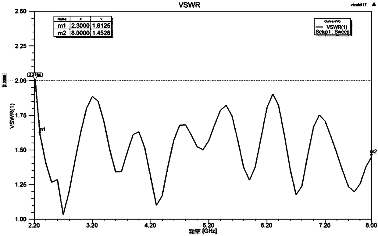
[0018] Such as figure 1 , figure 2 As shown, a kind of broadband high-gain Vivaldi antenna provided by the present invention comprises dielectric substrate 1, metal patch 2, quadrilateral metal patch 3, impedance matching microstrip line 4 and fan-shaped metal branch 5, metal patch 2 and quadrilateral metal patch The slices 3 are fixed on the top surface of the dielectric substrate 1, the impedance matching microstrip line 4 and the fan-shaped metal branch 5 are fixed on the bottom surface of the dielectric substrate 1, and the metal patch 2 has a trumpet-shaped opening symmetrical to its horizontal central axis. The gradual change groove line 6, the gradual change groove line 6 has an exponential gradual change, and its opening width should not be less than half of the wavelength corresponding to the lowest operating frequency. A circular r...
PUM
 Abstract
Description
Claims
Application Information