Antenna System with Gain Self-Correcting Function

An antenna system, self-calibration technology, applied in the direction of antenna, antenna support/installation device, electrical components, etc., can solve the problems of gain influence, failure to solve, and reduce system reliability, etc., to solve gain fluctuation and beam change, Amplitude and phase changes remain stable, adaptable effects

Active Publication Date: 2019-02-26
HEFEI UNIV OF TECH
View PDF6 Cites 0 Cited by
  • Summary
  • Abstract
  • Description
  • Claims
  • Application Information

AI Technical Summary

Problems solved by technology

[0003] 1. The increase of active devices and circuits will reduce the reliability of the system, especially the failure of active devices will cause the entire system to fail to work
[0004] 2. Active devices are usually enclosed in a cavity made of metal or other materials, and due to the heat dissipation of other power devices in the cavity, there will be a large gap between its temperature change and the outdoor ambient temperature, which cannot reflect the impact of temperature changes on the lens structure. influences
[0005] 3. The feedback signal usually collected by active devices comes from the output coupling signal of the final stage amplifier, so its gain stabilization circuit can only adjust the output signal of the final stage amplifier, but cannot achieve effective temperature self-control for the signal fed into the antenna system. adapt
But the disadvantage of this design is that the lens material will produce slight changes in structure as the temperature changes, and the changes of electromagnetic waves passing through the lens are very sensitive to these structural parameters of the lens, and small changes in the lens structure will affect the system. radiation characteristics, especially the gain has a noticeable effect on the
In summary, the existing dielectric lens-loaded antenna structure does not solve the above problems

Method used


Image

  • Antenna System with Gain Self-Correcting Function
  • Antenna System with Gain Self-Correcting Function
  • Antenna System with Gain Self-Correcting Function

Examples


Embodiment 1

[0125] Embodiment 1: 24GHz point-to-point mobile communication system

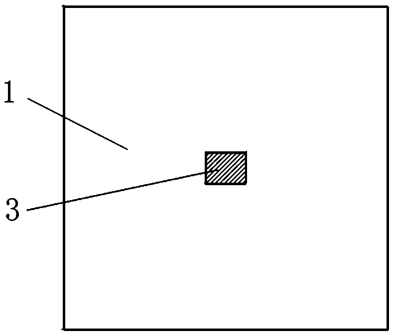
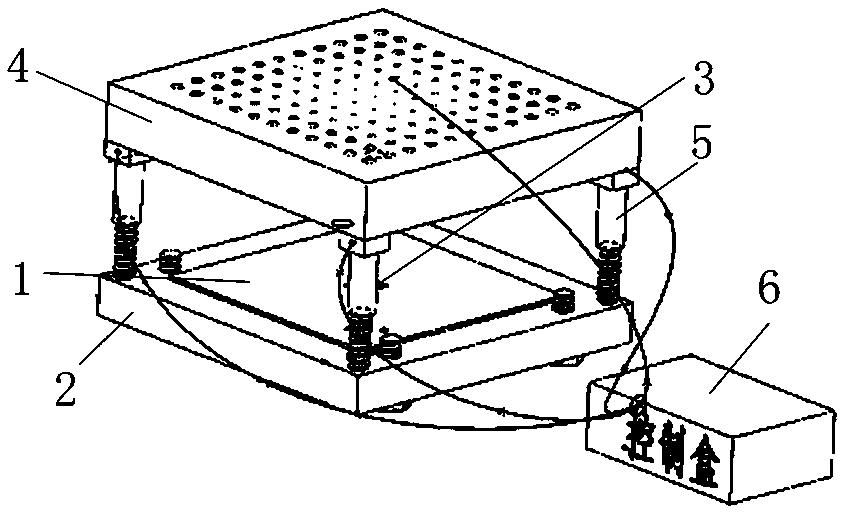
[0126] The invention adopts the following technical scheme: a temperature-adaptive high-gain antenna hardware part is mainly composed of a radiation antenna, a high-precision lifting rod and a dielectric lens. The radiating antenna 3 adopts a conventional microstrip patch structure, such as figure 1 shown. The size of the radiating antenna 3 whose structure is a microstrip patch is 3.76×5.02 mm, and the size of the substrate is 40×40 mm. The material of the microstrip patch substrate is ROS5880, the metal layer is copper with a thickness of 35um, and the plating layer is gold.

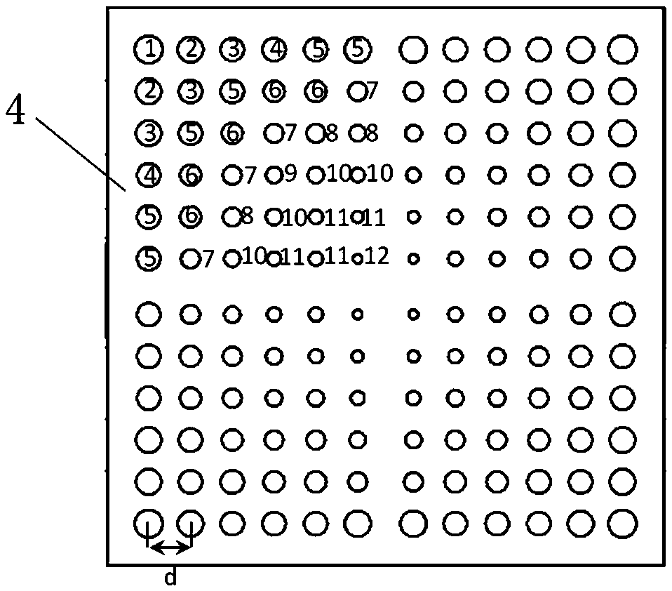
[0127] According to the radiation characteristics of the radiating antenna, the size of the dielectric lens is as follows figure 2 As shown, the size of the dielectric lens plate 4 is 54×54 mm. The dimension values ​​of the through hole pattern on the dielectric lens plate 4 are shown in Table 1.

[0128] Table 1: 24GHz Diele...

Embodiment 2

[0136] Embodiment 2: 60GHz point-to-point mobile communication system

[0137] The present invention adopts the following technical scheme: a temperature-adaptive high-gain antenna hardware part is mainly composed of a radiation antenna, a high-precision lifting rod and a dielectric lens, such as Figure 10 shown. The antenna composition of 60GHz point-to-point mobile communication system is basically the same as that of 24GHz, the difference is that the form of the radiating antenna is a symmetrical vibrator, the thickness of the metamaterial plate of the dielectric lens, the aperture, and the distance between the radiating antenna and other structural dimensions are set as follows. . The dielectric lens material is ROGES TMM10 with a dielectric constant of 9.2 and a thickness of 7.5mm. like Figure 9 As shown, the dimension values ​​of the through holes in the figure are set according to Table 3.

[0138] Table 3: 60GHz Dielectric Lens Through Hole Diameter and Hole Spac...


PUM


Abstract

Aiming at the problem that an existing antenna system with a dielectric lens does not consider a thermal expansion effect of the dielectric lens in a wide temperature range, the invention provides an antenna system having a gain auto-correction function. The antenna system comprises a substrate aluminum plate, a base, radiation antennas, a dielectric lens plate and a lifting device, wherein the base is arranged at the bottom of the substrate aluminum plate, the radiation antennas are arranged at the top of the substrate aluminum plate, the dielectric lens plate is arranged on the radiation antennas, the dielectric lens plate and the substrate aluminum plate are movably connected by the lifting device, and the relative distance between the dielectric lens plate and the radiation antennas is adjusted by the lifting device. The antenna system has the technical effects that a temperature change coefficient of the dielectric lens is adjusted by self-adaptive height adjustment, and the problems of gain fluctuation and beam change of the antenna system in the wide temperature range are effectively solved.

Description

technical field [0001] The invention belongs to the field of high-gain antennas with a wide temperature range, in particular to a dielectric lens-based microwave and millimeter-wave antenna gain automatic adjustment system, specifically an antenna system with a gain self-correction function. Background technique [0002] In recent years, the rapid development and functional requirements of microwave and millimeter wave communication systems with dynamic beam adjustment, high-gain perimeter protection radars, and high-gain detection equipment have greatly promoted the development of microwave and millimeter-wave antennas. At the same time, high-gain antennas have proposed more demanding. Since most microwave and millimeter wave systems are required to work outdoors, the ambient temperature varies from -40 degrees to 50 degrees. This not only requires the microwave circuit to have a high and low temperature adaptive processing system, but also requires that the antenna not on...

Claims


Application Information

Patent Timeline
Patent Type & Authority Patents(China)
IPC IPC(8): H01Q1/12H01Q3/46
CPCH01Q1/12H01Q3/46
Inventor 桑磊周豪刘刚芮金城李祥祥卢保军曹锐陶小辉
Owner HEFEI UNIV OF TECH
Why Eureka
Try Eureka